


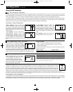
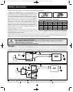
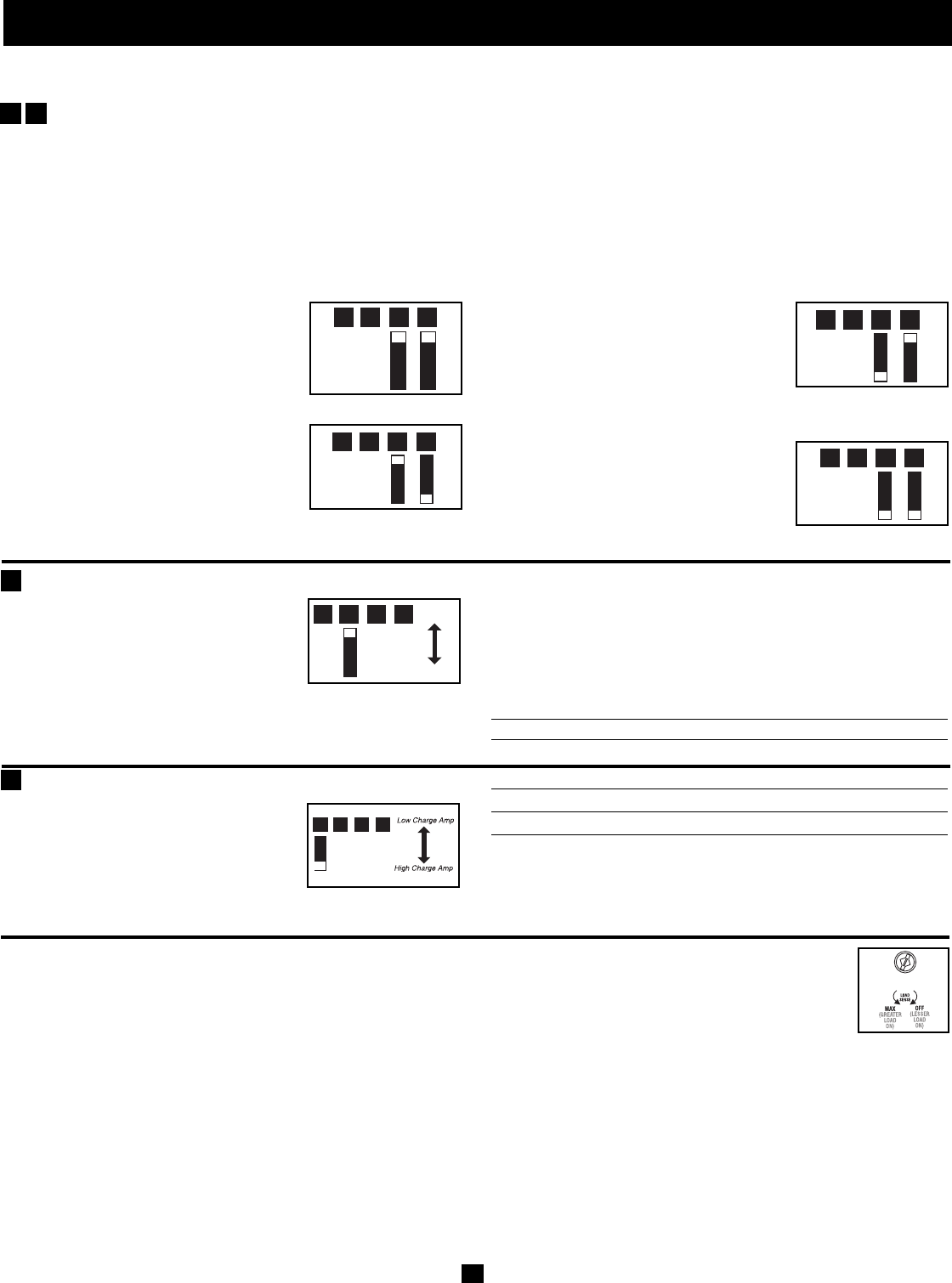
Select Battery Charger-Limiting Points
“Most Limiting” (#B2 & #B1 Up):
Charger-limiting takes effect the moment
any 120V AC load is applied; charger output
falls gradually from full output at no 120V
load passing through to no output at full load
(factory setting).
"Less Limiting" (#B2 Up & #B1 Down):
Charger-limiting begins when the
Inverter/Charger's load reaches 33% of the
Inverter/Charger's load rating. Charger out-
put falls gradually from full output at 33% of
the Inverter/Charger's load rating to about 33% of full output at full
load.
"Least Limiting" (#B2 Down & #B1 Up):
Charger-limiting begins when the
Inverter/Charger's load reaches 66% of the
Inverter/Charger's load rating. Charger out-
put falls gradually from full output at 66% of
the Inverter/Charger's load rating to about 66% of full output at full
load.
"No Limiting" (#B2 & #B1 Down): No
charger-limiting occurs at any load size.
Configuration
(continued)
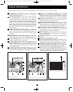
Group B DIP Switches
Select Load Sharing—OPTIONAL
Your Inverter/Charger features a high-output battery charger that can draw a significant amount of AC power from your utility source or gener-
ator when charging at its maximum rate. If your unit is supplying its full AC power rating to its connected heavy electrical loads at the same time
at this high charging occurs, the AC input circuit breaker could trip, resulting in the complete shut off of pass-though utility power.
To reduce the chance of tripping this breaker, all Inverter/Chargers automatically limit the input current as described in "Most Limiting" below.
Hardwired models may be set to other limiting options that allow greater amounts of charging power when full output power is passed through.
Verify that AC input wiring is rated for the higher current that results when using the other settings.
B2
B1
6
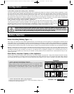
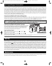
Set Battery Charging Amps—OPTIONAL
Check specifications for your unit’s high-
and low-charging amp options. By setting
on high charging, your batteries will
charge at maximum speed and your RV
12V DC system loads will be well-sup-
plied. When setting on low charging, you lengthen the life of your
batteries (especially smaller ones).
Battery Charger Switch Position
Low Charge Amps Up
High Charge Amps Down (factory setting)
CAUTION: When switching to the High Charge Amp setting, the user must ensure that the
amp hour capacity of their battery system exceeds the amperage of the High Charge Amp
setting or the batteries may be damaged or degraded.
Select Equalize Battery Charge—OPTIONAL
This DIP Switch is momentarily engaged to
begin the process of equalizing the charge
state of your battery’s cells by time-limited
overcharge of all cells. This can extend the
useful life of certain types of batteries; con-
sult with your battery’s manufacturer to determine if your batteries
could benefit from this process. The charge equalization process is auto-
matic; once started, it can only be stopped by removing the input power.
Setting Procedure
• Move to “Equalize” (DOWN) position for three seconds.
• Move to “Reset” (UP) position and leave it there. This is the
factory default setting.
CAUTION: Do not leave DIP switch #B3 in the down position after beginning process. Battery
charge equalization should only be performed in strict accordance with the battery manufacturer’s
instructions and specifications.
Battery Charge Switch Position
Reset Up (factory setting)
Equalize Down—momentarily
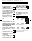
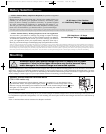
Set Battery Charge Conserver (Load Sense) Dial—OPTIONAL
In order to save battery power, the unit’s inverter automatically shuts off in the absence of any power demand from connected
equipment or appliances (the electrical load). When the unit detects a load, it automatically turns its inverter function on. Users
may choose the minimum load the Inverter/Charger will detect by adjusting the Battery Charge Conserver Dial (see diagram).
Using a small tool, turn the dial clockwise to lower the minimum load that will be detected, causing the inverter to turn on for
smaller loads. When the dial is turned fully clockwise, the inverter will operate even when there is no load. Turn the dial coun-
terclockwise to increase the minimum load that will be detected, causing the inverter to stay off until the new minimum load is reached.
Note: the factory setting for the dial is fully clockwise. However, based on the threshold load to which you’d like the inverter to respond, you should adjust the dial counterclockwise to reduce its sensitivity
until the inverter is active only when connected equipment or appliances are actually in use.
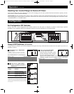
Connect Remote Control—OPTIONAL
All models feature an 8-conductor telephone style receptacle on the front panel for use with an optional remote control module (Tripp Lite model APSRM,
sold separately or included with select models). The remote module allows the Inverter/Charger to be mounted in a compartment or cabinet out of sight,
while operated conveniently from within the living area or control panel of your RV. See instructions packed with the remote control module.
B4
B3
B1B2B3B4
Reset
Equaliz
e
B1B2B3B4
B1B2B3B4
B1B2B3B4
B1B2B3B4
B1B2B3B4
200712159 93-2768 RV Series Inverter-Charger Owner’s Manual_Eng.qxd 2/29/2008 1:55 PM Page 6