


Configuration
(continued)
7
Battery Selection
Select Auxiliary Battery Type (if any)
Select “Deep Cycle” batteries to receive optimum performance from your Inverter/Charger. Do not use ordinary car or starting batteries or batteries rated in
Cold Cranking Amps (CCA). If the batteries you connect to the Inverter/Charger are not true Deep Cycle batteries, their operational lifetimes may be significantly
shortened. If you are using the same battery bank to power the Inverter/Charger as well as DC loads, your battery bank will need to be appropriately
sized (larger loads will require a battery bank with a larger amp-hour capacity) or the operational lifetimes of the batteries may be significantly shortened.
Batteries of either Wet-Cell (vented) or Gel-Cell /Absorbed Glass Mat (sealed) construction are ideal. 6-volt “golf cart”, Marine Deep-Cycle or
8D Deep-Cycle batteries are also acceptable. You must set the Inverter/Charger’s Battery Type DIP Switch (see Configuration section for more
information) to match the type of batteries you connect or your batteries may be degraded or damaged over an extended period of time. In
many cases, the vehicle battery may be the only one installed. Auxiliary batteries must be identical to the vehicle batteries if they are con-
nected to each other.
Match Battery Amp-Hour Capacity to Your Application
Select a battery or system of batteries that will provide your Inverter/Charger with proper DC voltage and an adequate amp-hour capacity
to power your application. Even though Tripp Lite Inverter/Chargers are highly-efficient at DC-to-AC inversion, their rated output capacities
are limited by the total amp-hour capacity of connected batteries and the support of your vehicle’s alternator if the engine is kept running.
Ignition Interlock Control function (optional): This function automatically disables (turns OFF) AC power
output from the Inverter/Charger when the vehicle’s ignition switch is placed in the “Engine Run” position.
This function will satisfy local codes and requirements concerning video monitors or TVs that are located
within a driver’s view by automatically turning them off when the engine is started.
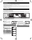
Connect Battery Temperature Sensing Cable—OPTIONAL
The battery temperature sensing function prolongs battery life by adjusting the charge float voltage level based on battery temperature. Connect
the sensor cable (the cable, included with select models, has an RJ style connector on one end and a black sensor on the other) to the RJ style
jack located on the side of the Inverter/Charger labeled “Remote Temp. Sense.” With user-supplied electrical or duct tape, affix the sensor to the
side of the battery below the electrolyte level. Make sure that nothing, not even tape, comes between the sensor and the side of the battery. To
guard against false readings due to ambient temperature, place the sensor between batteries, if possible, or away from sources of extreme heat
or cold. If the sensor cable is not used, the Inverter/Charger will charge according to its default 25º C values.
Utilize Automatic Generator Starter Capability—OPTIONAL
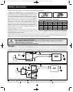
All models except 612 models include an RJ type modular jack on the side panel labeled “Generator Start”. Attach to
vehicle generator ON/OFF switching mechanism with user-supplied cable (see Pin Configuration Diagram). Once
attached, the interface will allow the Inverter/Charger to automatically switch a vehicle generator on when connected
battery voltage levels are low (11.6 VDC) and switch it off when battery voltage levels are high (14.1 VDC).
1
2
3
4
5
6
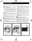
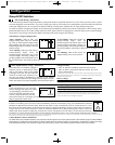
Pin Configuration
2 - Common
3 - N.C.
(Normally Closed)
4 - N.O.
(Normally Open)
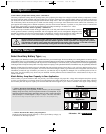
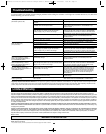
Example
Tools
300W + 220W + 20W = 540W
¼" Drill
Orbital Sander
Cordless Tool Charger
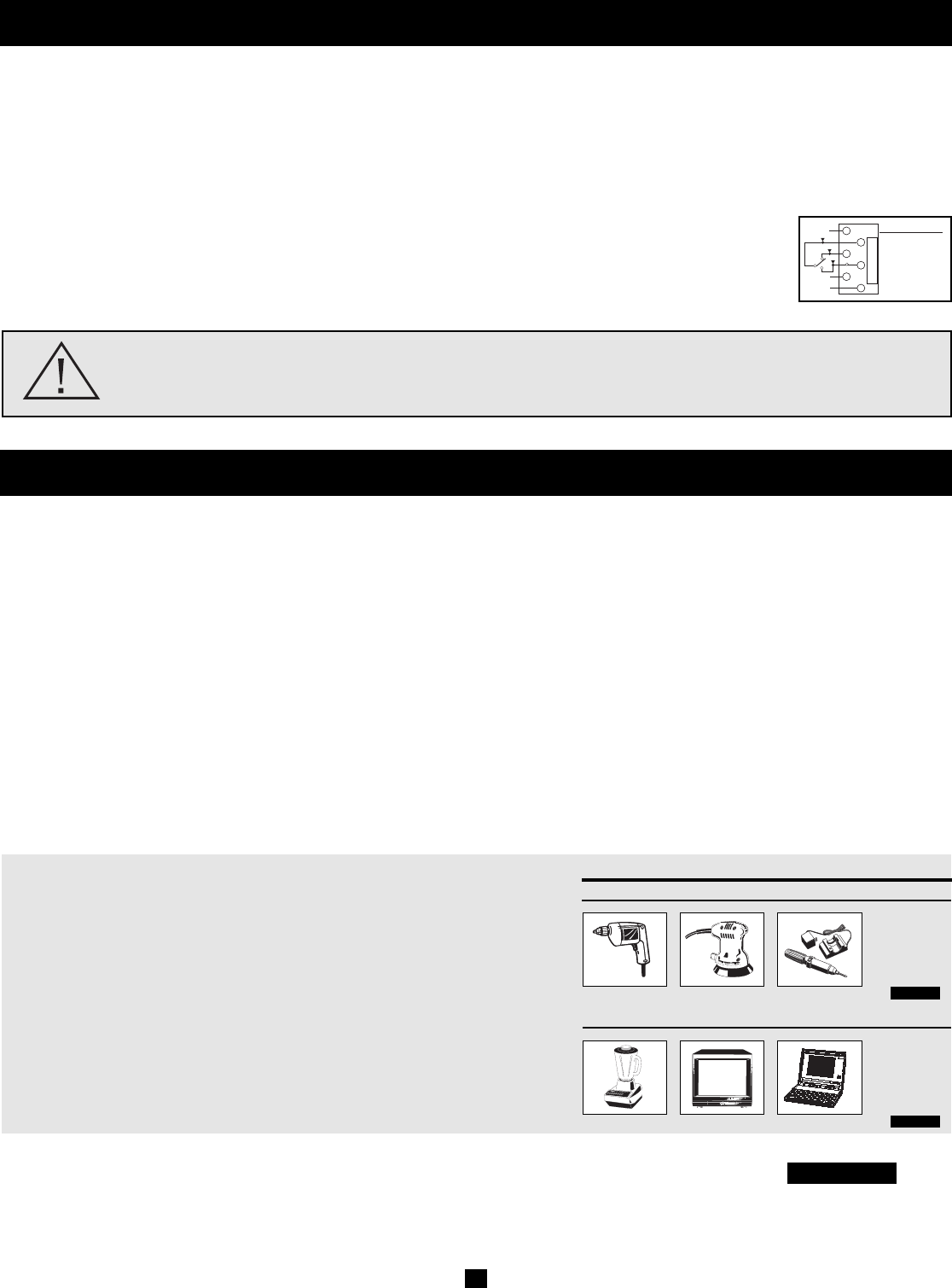
Appliances
300W + 140W + 100W = 540W
Blender Color TV Laptop Computer
• STEP 1: Determine Total Wattage Required
Add the wattage ratings of all equipment you will connect to your Inverter/Charger.
Wattage ratings are usually listed in equipment manuals or on nameplates. If your
equipment is rated in amps, multiply that number times AC utility voltage to determine
watts. (Example: a ¼ in. drill requires 2½ amps. 2½ amps × 120 volts = 300 watts .)
Note: Your Inverter/Charger will operate at higher efficiencies at about 75% - 80% of nameplate rating.
• STEP 2: Determine DC Battery Amps Required
Divide the total wattage required (from step 1, above) by the battery voltage (12)
to determine the DC amps required.
540 watts ÷ 12V = 45 DC Amps
200712159 93-2768 RV Series Inverter-Charger Owner’s Manual_Eng.qxd 2/29/2008 1:55 PM Page 7