


6
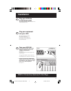
This multi-colored light displays 4 separate UPS load conditions.
It will turn from green (low) to yellow (medium) to red (high) as you
connect equipment to show you the load level your UPS is support-
ing. When the light is red your UPS is supporting a load above 85%
of its capacity. If the red light begins flashing, your UPS is severely
overloaded. Remove overload immediately until light stops flashing.
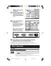
Other UPS Features
L6-20 AC Receptacle
This locking receptacle provides your connected equipment with
AC line power during normal operation and battery power during
blackouts and brownouts. It also protects your equipment against
damaging surges and line noise. You can remotely reboot con-
nected equipment by turningthe UPS OFF and ON using Tripp Lite
UPS software. See software instructions for details.
SMART/LAN 4.1 (RS-232) Port
The RS-232 port connects your UPS to any workstation or server.
Use with Tripp Lite software and cabling to monitor and manage
network power and automatically save open files and shut down
equipment during a blackout. This port uses RS-232 communica-
tions to transmit UPS and power conditions. Select models feature
plug-and-play capability. Contact Tripp Lite Customer Support for
more information and a list of available SNMP, network manage-
ment and connectivity products.
BASIC/LAN 2.2 (Contact Closure) Ports (2)
Also used to connect your UPS to any workstation or server. Use
with Tripp Lite software and cabling to automatically save open
files and shut down equipment during a blackout. These ports use
contact-closure signals to indicate line-fail and low-battery status.
External Battery Connector
Use this to connect additional Tripp Lite battery packs for addi-
tional runtime. Refer to the label next to the connector for
appropriate Tripp Lite battery pack to connect. Refer to instruc-
tions available with the battery pack for complete connection
information and safety warnings.
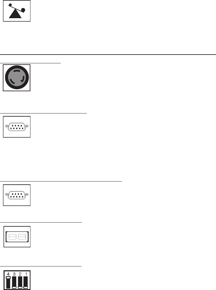
LAN Interface DIP Switches
DIP Switches #1 and #2 activate or deactivate remote shutdown
through the “BASIC” Contact-Closure Ports. See “DB9 Port Con-
nection” on page 4 for which switch controls which port. Note: DIP
Switch #3 has no function. DIP Switch #4 serves as
the UPS’s “System Enable Switch.”
9911081 230V Smartpro 2200T OM.p65 11/24/99, 12:00 PM6