3
Control Panel
There are two separate UPS system modules: a power module and a battery module. Familiarize yourself with the location and function of
the features on each module before installing and operating your UPS system. The power module is the only module which includes front
panel features.
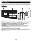
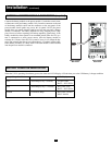
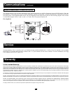
FRONT PANEL
1. "ON/OFF" Switch: This momentary rocker switch turns the UPS System's inverter ON and OFF.
2. "SELECT" Button: This button performs two functions: it allows you to browse through different power readings on the LCD Display
by momentarily pressing the button; it also allows you to silence the UPS alarm by pressing and holding the button for 3 seconds.
3. LCD Display: This backlit (16x2 character) dot matrix display indicates a wide range of UPS operating conditions and diagnostic data.
It will illuminate after you have properly completed installation and start-up and after the "ON/OFF" Switch is turned ON.
4. "I/P" (Input) LED: This green light will illuminate constantly to indicate an AC input supply is present.
5. "AC/DC" (Converter) LED: This green light will illuminate constantly to indicate the UPS's AC/DC converter is activated.
6. "DC/AC" (Inverter) LED: This green light will illuminate constantly to indicate the UPS's DC/AC inverter is activated.
7. "O/P" (Output) LED: This green light will illuminate constantly to indicate your UPS is supplying AC power to connected equipment.
8. "BYPASS" LED: This green light will illuminate when the UPS is providing filtered mains power without engaging its converter or
inverter. Connected equipment will not receive battery power in the event of a blackout.
9. "BATTERY" LED: This red light will illuminate when the UPS is discharging the battery to provide connected equipment with AC
power. An alarm will sound which can be cancelled by pressing and holding the "SELECT" switch for 3 seconds. The alarm will be can-
celled, but the LED will remain illuminated.