


5
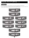
Rear Panels
(continued)
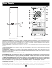
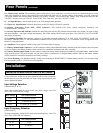
10. “Battery Start” Switch: This momentary rocker switch allows you to “cold-start” your UPS and use it as a stand-alone power source
when utility-supplied AC power is not present. The switch enables the UPS’s DC/AC Inverter. Before “cold-starting” your UPS, make sure
your power module and external battery module(s) are properly installed. Press and hold the “Battery Start” Switch and then press the
“ON/OFF” switch to turn your UPS ON. To turn it OFF after “cold-start,” press the “ON/OFF” Switch.
11. AC Input Breaker: Controls input power to the UPS during normal operation.
12. Bypass AC Input Breaker: Controls input power to the UPS during “BYPASS” operation.
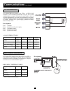
13. Remote “Emergency Power OFF” (EPO) Connector: This modular jack allows remote emergency shutdown. See
“Communications” for details.
14. Inverter Operation DIP Switches: Behind this removable panel are four DIP Switches that should be set to match your input voltage
and input frequency. Your input voltage and frequency DIP switch settings MUST match your input. Your UPS WILL NOT CONVERT
the voltage or frequency.
15. Grounding Terminal: This terminal connects to a grounding electrode conductor. IT IS NOT SAFE TO OPERATE YOUR UPS
WITHOUT CONNECTING IT. The recommended conductor size is 6 AWG based on the UL 1778 standard. Follow all applicable local
electrical wiring regulations.
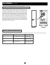
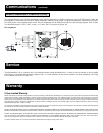
16. Stabilizers: These supports extend to keep your UPS from rolling or tipping.
17. Battery Module Input Connector: Use this connector to daisy-chain additional battery modules to the first. Remove the cover panel
for access. Refer to the battery module's owner's manual for connection instructions and safety warnings.
18. Battery Module Output Cable: Use this cable to connect the battery module to the power module (or to another battery module when
using more than one). The power module will not start without a connection to a charged battery module. Refer to the battery module
owner's manual for connection instructions and safety warnings.
19. Tower Mounting: For additional stability during tower mounting of BP240V10RT3U External Battery Module, you can order Tripp
Lite base stands (model #: 2-9USTAND) sold separately.
Installation
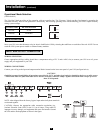
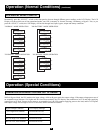
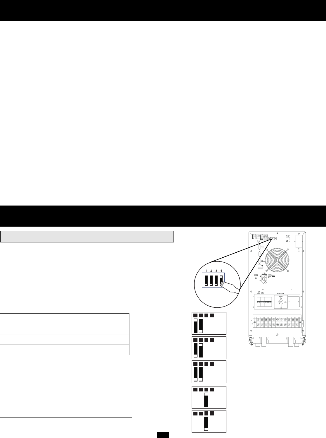
INVERTER OPERATION DIP SWITCH SETTINGS
Using a small tool, set the four Inverter Operation DIP Switches (located on
the rear panel of your UPS) to match your input voltage, input frequency and
desired operational mode.
Input Voltage Selection
(DIP Switches #1 & #2)
These DIP switches must be set to match your input voltage. Your UPS
WILL NOT CONVERT the voltage.
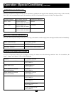
Input Voltage DIP Switch Position
220V #1 UP & #2 DOWN
230V #1 DOWN & #2 UP
240V #1 DOWN & #2 DOWN
Input Frequency Selection
(DIP Switch #3)
Your Input Frequency setting MUST match your input frequency. Your UPS
WILL NOT CONVERT the frequency.
Input Frequency DIP Switch Position
50 Hz #3 UP
60 Hz #3 DOWN
REFER TO USER'S MANUAL FOR TORQUING
SPECIFICATIONS, USE COPPER CONDUCTORS ONLY.
UTILISER SEULEMENT LES CONDUCTEURS DE CUIVRE.
1 2 3 4
220V
1 2
230V
3 4
1 2
240V
3 4
1 2
50 Hz
3 4
1 2
60 Hz
3 4