


3
Mounting
Note: When removing the mounting bracket screws to change the mounting profile of your UPS, do not remove the
screws which secure the UPS cabinet. Two of these screws are located at each end of the UPS, between the four holes
used for the mounting brackets.
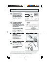
Rackmount
Your UPS’s mounting brackets are pre-set at a standard depth for 19-in. rack
installation.* Additional bracket holes allow you to mount the UPS at additional
depths. To adjust the depth: Remove mounting bracket screws; adjust brackets
to the desired depth; replace screws.
Desktop/Under-Monitor
Remove mounting brackets (if desired). Place on your desktop or under your com-
puter monitor. CAUTION: Do not place more than 50 lb. (22.7 kg) on your UPS.
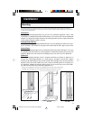
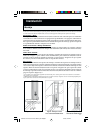
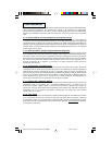
Vertical Tower
Remove mounting bracket screws. Position brackets as shown in Figure 1 to serve
as stabilizers for the UPS in a vertical position. Install 2 mounting screws in each
bracket. Make sure the control and LED panel is UP when you are finished.
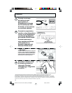
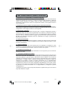
Wallmount
Remove mounting bracket screws. Position brackets as shown in Figure 2 to
mount the UPS perpendicular to a wall along a straight, vertical line. Adjust
bracket to desired distance from wall. Install 4 mounting screws in each bracket.
Mount UPS to the wall.* Make sure the control and LED panel is UP when you
are finished. Additional bracket holes allow you to mount up to two UPSs side-
by-side on the same set of brackets (Figure 3).**
* Using screws and appropriate hardware (user supplied) to mount to rack, wall or other surface.
** CAUTION: each UPS weighs 15-1/2 lbs. (7 kg). Ensure adequate wall fasteners are used.
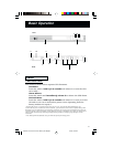
Installation
Figure 1 – Vertical Tower
Figure 2 – Wallmounting
One UPS
Figure 3 – Wallmounting
Two UPSs
9904216 Smart 450 RT Owners Manual [120 Volt].p65 3/13/00, 3:02 PM3