


Your UPS may be rackmounted in 4- or 2-post racks using these suggested mounting procedures. The procedures are for common
rack types and may not be appropriate for all rack configurations. User must determine the fitness of rackmount hardware and pro-
cedures before mounting.
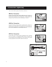
Color Selection
Your UPS is shipped with a grey front panel, 2 grey mounting ears and 2 black mounting ears. To match grey equipment, mount the
grey ears in front. If you would like your UPS to match black equipment, you may request the alternate (black) front panel for 3U UPS
systems (Tripp Lite part #AC4134) by calling (773) 869-1234.
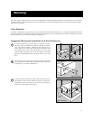
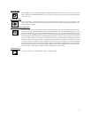
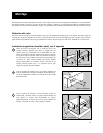
Suggested Rackmount Installation for 4-Post Enclosures
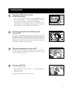
Loosen the wingnuts (A) on each of the two adjustable side sup-
ports (B); adjust the length of the supports to match the depth of
your rack; tighten wingnuts. Mount both side supports in the
lowest space of your rack on the inside surfaces of the rails with
user-supplied #10-32 rack bolts and washers (C). Note: Both
support ledges should face inward. The side supports’ front and
back holes are threaded and do not require nuts to secure rack
bolts.
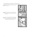
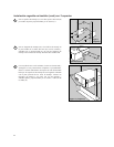
Attach mounting ears (D) to the front mounting holes of the UPS
(E) using the screws and washers provided (F). Do not attach the
mounting ears to the UPS’s middle holes.
Using an assistant if necessary, lift the UPS and slide it onto the
side supports within your rack. Mount the UPS by screwing user-
supplied rack bolts (G) through its mounting ears, through the
rack rails and through the side supports.
D
F
E
C
B
C
A
G
3
Mounting
Figure 3 (4-Post)
Figure 1 (4-Post)
Figure 2 (4-Post)
3
2
1
C
B
A
C
E
D
F
G