


8
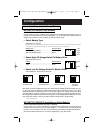
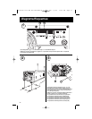
Mounting (Optional*)
(See Diagram 2, p. 32).
User must supply all fasteners and brackets and verify their suitability for use with the intended
mounting surface. Turn your APS PowerVerter and connected equipment OFF before mounting.
• Install two 8 mm (1/4 in.) fasteners (A) into a rigid horizontal surface using the measurements
in the diagram. Leave the heads of fasteners raised slightly above the surface in order to
engage the slots in the APS’s feet.
• Slide PowerVerter forward to fully engage the fasteners in the APS’s feet. Install two 8 mm
(1/4 in.) fasteners (B) into the surface, through the slots in the APS’s two unsecured feet.
Tighten the screws to secure the APS in position.
* Horizontal mounting should be used for all vehicular applications. Due to their size and weight, all APS PowerVerter
systems in vehicles should be mounted on a rigid horizontal (not vertical) surface, mounting plate or bracket before
battery connection.
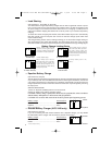
Battery Connection (Standard)
1. Connect your APS’s positive DC Terminal directly to a fuse.
UL recommends that you install a recognized UL component fuse block and fuse within 18 inches
of the battery.The fuse's rating must equal or exceed the Minimum DC Fuse Rating listed in your
APS model's specifications on pages 14 or 15.
2. Choose a battery configuration appropriate to your batteries.
• Single Battery Connection: Refer to Diagram 4, page 33. When using a single battery, its
voltage must be equal to the voltage of your APS's Inverter Nominal Input Voltage (see
specs).
• Parallel Battery Connection: Refer to Diagram 5, page 33.When using multiple batteries in
parallel, each battery's voltage must be equal to the voltage of your APS's Inverter Nominal
Input Voltage (see specs).
• Series Battery Connection: Refer to Diagram 6, page 33. When using multiple batteries in
series, all batteries must be equal in voltage and amp hour capacity, and the sum of their
voltages must be equal to the voltage of your APS's Inverter Nominal Input Voltage (see
specs).
3. Use 2/0 gauge wire ONLY to make external battery connections.
Tighten battery terminals to a torque of 4 N-m.
WARNING! Failure to follow these instructions can lead
to product failure due to excessive heating!
Battery connection cable lengths should be short as possible, and must not exceed the
Maximum Cable Length listed under Specifications, page 14.Shorter and heavier gauge cabling
limits DC voltage drop and allows for maximum transfer of current.* You must tighten your battery
terminals to approximately 4 Newton-meters of torque to create an efficient connection and prevent
excessive heating. Insufficiently tightening terminals could void your PowerVerter's warranty.
*APS models are capable of delivering a much higher wattage output for brief periods of time. Wiring should be configured to
handle this brief high-current draw. Though your APS is a high-efficiency converter of electricity, its rated output capacity is limited
by the length and gauge of the wires running from the battery to the APS.
Battery Connection (DC Vehicular)
APS systems may be permanently mounted in a car, truck or boat and connected to draw power
from the vehicle's battery. Note: An APS can ONLY be connected to vehicle batteries with
voltage that matches the APS's Nominal DC Input—12V vehicle batteries to 12V Nominal DC
Input APS systems, etc. (See Specifications). There are two main ways to make this sort of
200103046 120V APS MV-cabinetEn-Sp 93-1911.qxd 7/2/01 10:18 AM Page 8