


9
vehicular battery connection. Choose the Basic Connection if you are running light hand tools or
other small appliances for a brief period of time (see Diagram 7, p. 34). Choose the Advanced
Connection if you are using your APS to power heavy loads for extended periods of time (see
Diagram 8, p. 34).The Advanced Connection incorporates a battery isolator and separate battery
system to provide battery power to your APS while preventing it from draining your vehicle's
battery. Note: Depending on your application, you may require more than one Deep Cycle Battery.
Caution: Never operate your APS from an alternator without a battery connected as shown in Diagrams 7 or 8, p. 34.
AC Connection
Before AC connection, match the power requirements of your
equipment with the power output of your APS to avoid overload.
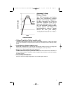
When figuring the power requirements of your equipment, do not confuse “continuous” power
ratings with “peak” power ratings. Electric motors require more power to turn on (“peak power”)
than they require to run continuously. “Peak” power ratings are usually 2 to 5 times “Continuous”
ratings. Most electric motors require “peak power” only when they are first turned on. The electric
motors in equipment such as refrigerators and sump pumps, however, constantly turn on and off
according to demand. These motors require “peak power” at multiple, unpredictable times during
their operation.
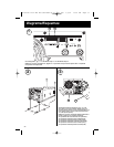
Hardwired Electrical Connections
(All hardwire models)
(See Diagram 3, p. 32).
Consult a qualified electrician and follow all applicable electrical codes and requirements.
HARD
WIRE PROCEDURE
1) Remove screws and cover plate from your APS's Hardwire AC electrical box. Remove the
knockout covers closest to the desired electrical source and to your equipment.
2) Thread your wires through strain reliefs and through the knockouts.
3) Connect both input and output ground wires to the ground (green) terminal.
4) Connect the incoming hot wire to the input hot (brown) terminal.
5) Connect the incoming neutral wire to the input neutral (blue) terminal.
6) Connect the outgoing hot wire to the output hot (black) terminal.
7) Connect the outgoing neutral wire to the output neutral (white) terminal.
8) Tighten and affix strain reliefs. Replace cover plate and tighten screws.
AC Input Electrical Connection
(All corded models)
Plug the line cord into an outlet providing 120V AC, 60 Hz. power. Make sure that the circuit you
connect your APS to has adequate overload protection, such as a circuit breaker or a fuse.
AC Output Electrical Connection
(All corded models)
Simply plug your equipment into the unit's AC receptacles
Set Operating Mode Switch
• Switch to “AUTO/REMOTE” when you are using connected equipment. ADVANTAGE:
Uninterruptible power supply. Provides battery backup power during blackouts or brownouts.
Note:When the switch is in the “AUTO/REMOTE”position, you can operate a user-supplied
switch to transfer between battery-backup and charge-only modes. (See Remote
Connector manual for more information.)
200103046 120V APS MV-cabinetEn-Sp 93-1911.qxd 7/2/01 10:18 AM Page 9