


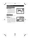

Rear Panel
continued
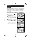
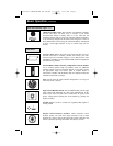
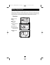
Input Cord Connection: This IEC320-C20 or IEC320-C14 inlet
enables the UPS to be connected to an AC power source via a
user-supplied cord with country-specific plug. See "Connection and
Start-Up".
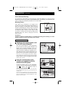
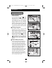
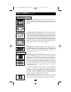
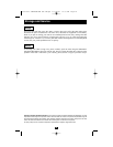
AC Receptacles (Varied by Model): These receptacles provide your
connected equipment with pure sine-wave AC output from the AC
line during normal operation and from battery power during blackouts
and severe brownouts. Power provided at these outlets is filtered to
protect connected equipment against damaging surges and line noise.
Select models feature receptacles arranged in numbered load banks,
as labelled on the unit. Using PowerAlert software and cabling, load
banks can be individually turned off and on from a remote location,
allowing users to reset or reboot connected equipment.
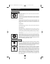
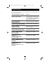
Telephone/Network Protection Jacks: These jacks protect your
equipment against surges over a telephone line or telephone/network
data line. Connecting your equipment to these jacks is optional. Your
UPS will work properly without this connection.
Not compatible with PoE
(Power Over Ethernet) applications.
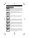
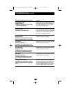
Communications Ports (USB or RS-232): These ports connect your
UPS to any workstation or server. Use with Tripp Lite’s PowerAlert
Software and included cables to enable your computer to
automatically save open files and shut down equipment during a
blackout. Also use PowerAlert Software to monitor a wide variety of
AC line power and UPS operating conditions. Consult your
PowerAlert Software manual or contact Tripp Lite Customer Support
for more information. See “USB and RS-232 Serial
Communications” in the “Optional Connections” section for
installation instructions.
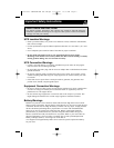
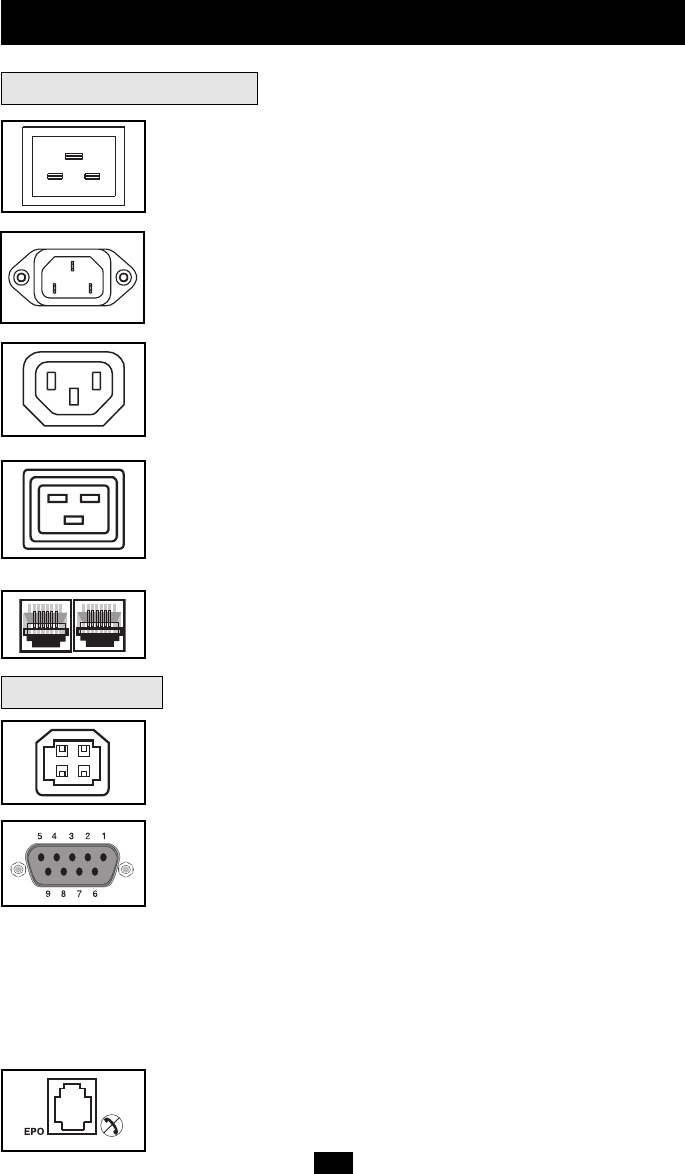
Dry contact communications are simple, but some knowledge of
electronics is necessary to configure them. The DB9 port's pin
assignments are shown in the diagram. If the UPS battery is low, the
UPS sends a signal by bridging pins 1 and 5. If utility power fails, the
UPS sends a signal by bridging pins 8 and 5. To shut the UPS down
remotely, short pin 3~pin 9 for at least 3.8 seconds.
EPO (Emergency Power Off) Port: Your UPS features a EPO port
that may be used to connect the UPS to a contact closure switch to
enable emergency inverter shutdown. See "Optional Connections."
IEC320-C13
IEC320-C19
Communications
10
Basic Operation
(continued)
IEC320-C20
IEC320-C14
200703028--SMARTONLINE UPS OM.qxd 4/13/2007 10:56 AM Page 10