


11
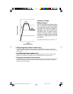
8. "BATTERY HI/MED/LO" (All models)
These three lights will turn ON in several sequences to show the approximate charge level and voltage
of your connected battery bank and alert you to several fault conditions:
BATTERY CHARGE INDICATION (Approximate)
Indicator Capacity
Green Full
Green & yellow 80% - Full
Yellow 60% - 80%
Yellow & red 40% - 60%
Red 20% - 40%
All three lights off 0% - 20%
Flashing red 0% (Inverter shutdown)
All three lights flash slowly* Excessive discharge
All three lights flash quickly** Overcharge
* Approximately 1/2 second on, 1/2 second off. See Troubleshooting section.
** Approximately 1/4 second on, 1/4 second off. May also indicate a battery charger fault exists. See Troubleshooting section.
Other Features
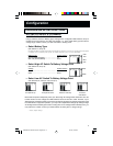
9. DC Input Terminals (All models)
The terminals' lug screws secure the wires leading from your external battery or battery system.
Your battery or battery system must provide your APS with proper DC voltage and your equipment
with an adequate amp hour capacity. See Battery Selection section, pg. 7 for more information.
10. AC Receptacles (Corded models only)
These receptacles allow you to plug equipment into the APS as it would be plugged into a utility outlet.
11. AC Input Line Cord (Corded models only)
This cord should be plugged into a dedicated 15 Amp AC utility outlet that provides power of an
appropriate voltage and frequency. DO NOT plug the cord into the APS’s AC receptacles.
12. Hardwire AC Input/Output Terminal Strip (Hardwire models only)
Use the lug screws on these terminals to secure hardwire connections for AC input and output. See
pages 9 & 33 for wiring instructions.
13. Resettable Circuit Breaker (All models)
The circuit breaker protects your APS against damage due to output overload. If the breaker trips,
remove some of the load on the APS to prevent overload, then wait 1 minute to allow components
to cool before resetting the circuit breaker.
14. Remote Module Connector (All models)
The front panel of all models has an RJ 45 receptacle for use with the optional remote module. (Module
is included with all VR models.) See the installation instructions packed with the remote module.
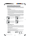
15. Load Sense Potentiometer (All models)
In order to save battery power, the APS's inverter automatically shuts off when no load is connected.
When the unit detects a load, it automatically turns the inverter on. Users may choose the minimum
load the APS will detect by adjusting the Load Sense Potentiometer. Using a small tool, turn the
potentiometer clockwise to lower the minimum load that will be detected, causing the inverter to turn
on for smaller loads. When the potentiometer is turned fully clockwise, the inverter will operate even
when there is no load. Turn the potentiometer counterclockwise to increase the minimum load that
will be detected, causing the inverter to stay off until the new minimum load is reached. The factory
setting for the potentiometer is fully clockwise, but in areas with frequent power interruptions, the
potentiometer should be adjusted counterclockwise until the inverter is only in operation when the
APS's load is in use.
9906058 230V APS MV-cabinet--English.p65 3/21/00, 4:29 PM11