


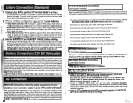
This manual contains important instructions and warnings that should be followed during the
installation, operation and storage of all Tripp Lite APS Systems.
APS
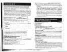
Location Warnings
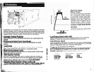
Install your APS indoors, away from excess moisture or heat, dust or direct sunlight.
Leave adequate space around all sides of the APS for proper ventilation. The heavier the
load of connected equipment, the more heat will be generated by the APS.
--
*-
Do
noti
thdPS
marmagneticstorage
media;-asthis mayresult In data
wrmpttan~
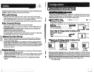
Battery Connection Warnings
You must connect batteries in order for any APS model to operate.
Multiple battery systems must be made up of batteries of the same voltage, age, amp
hour capacity and type.
Keep battery location well ventilated. Explosive hydrogen gas can accumulate near
batteries
if
they are not kept well ventilated.
Sparks may result during final battery connection.
Do not allow objects to contact the two DC input terminals. Do not short or bridge these
terminals together. Serious injury to property or person could result.
luipment Connection Warnings
I
Do
not use Tripp Lite APS Systems in life support applications where a malfunction or
failure of a Tripp Lite APS System could cause failure or significantly alter the perfor-
mance of a life support device.
Do not connect a surge suppressor, line conditioner or UPS to the output of the APS.
Corded models: Do not remove or modify the ground pin of the APS's plug. Do not use
Weprong adaptors with the APS's plug. Connect your APS only to a properly grounded,
three-wire AC power outlet.
Do
not plug your APS into itself; this will damage the APS
and
void your warranty.
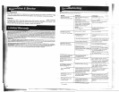
nperation Warnings
Your APS does not require routine maintenance. Do not open your APS for any reason.
There are no user-serviceable parts inside.
Potentially lethal voltages exist within this unit as long as the battery supply is connected.
During any
service work, the battery supply and AC input connection (if any) should
therefore be disconnected.
Do not connect or disconnect batteries while the APS is operating from the battery
supply.
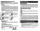
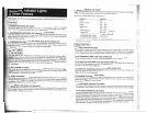
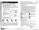
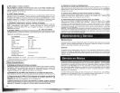
CONFIGURATION DIP SWITCH SETTINGS
DIP SWITCH GROUP A (All models1
BA77ERY
TYPE/
VOLTAGE POINT
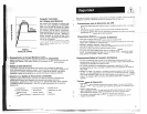
Using a small tool,
set
the
4
'Battery Type
I
Voltage Point" Configuration DIP Switches, Group A
(located on the front panel of your APS; see Diagram 1,
p.
32) to select battery type and set the
!
voltage range outside of which your APS will switch to battery power.
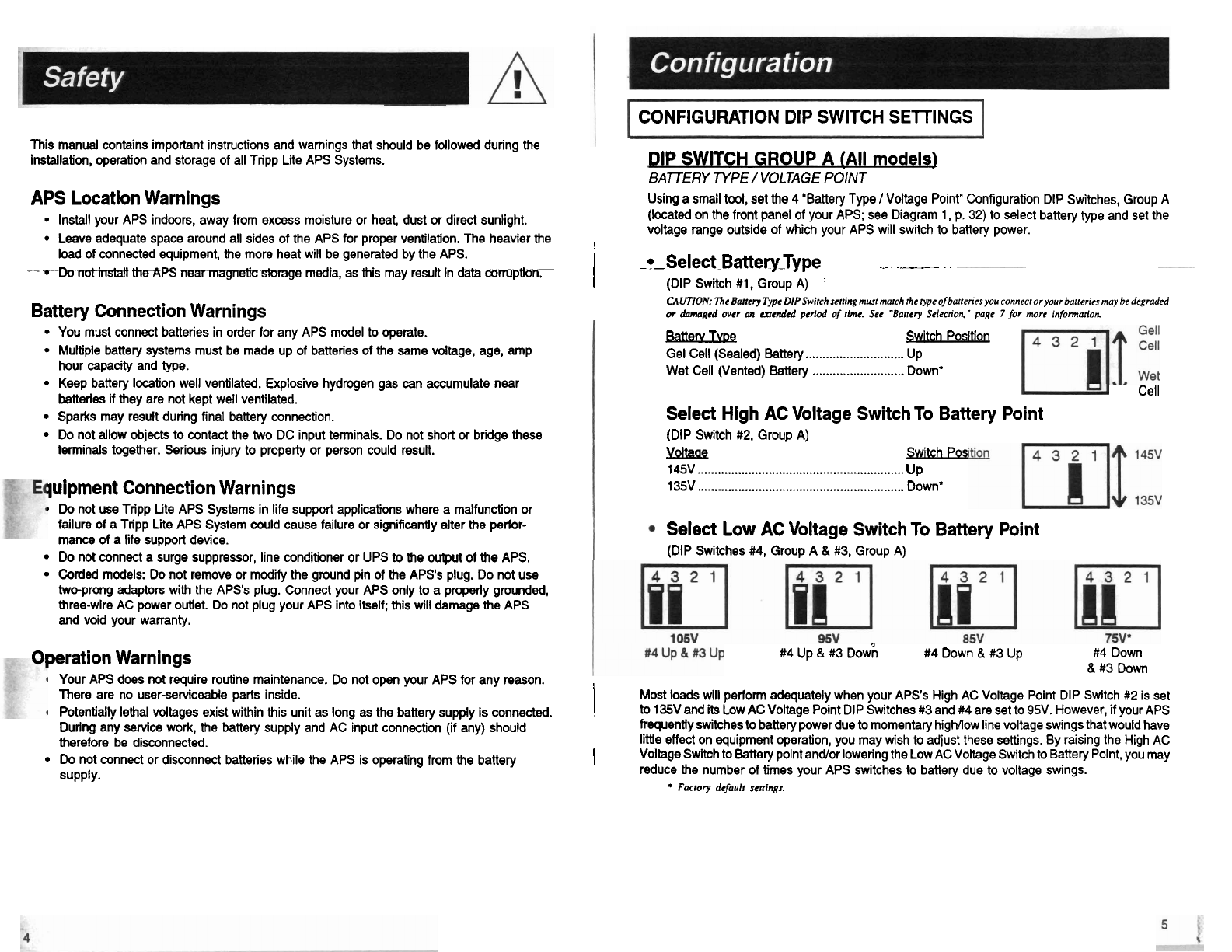
Select -Battery_Type
-
~p
~.-
~
~~
~
(DIP Switch #1, Group A)
'
CALITION:
The Banery Type
DIP
Switch sening must march rhe type of banerirs you connecr or your hunerics may he degraded
or
damaged over
an
mended period of rime. See "Barrcry Selecrion." page
7
for more infomarion
Batkum~
&itch Posltlon
.
.
Gel Cell (Sealed) Battery
.............................
UP
Wet Cell (Vented) Battery ........................... Down*
Cell
Select High AC Voltage Switch To Battery Point
(DIP Switch #2. Group A)
.
,
YQ&Q
Switch Pos
145V
.............................................................
UP
135V
.............................................................
Down'
Select Low AC Voltage Switch To Battery Point
(DIP Switches #4, Group A
&
#3,
Group A)
#4 Up
&
#3
own
#4 Down
&
#3 Up
#4 Down
&
#3 Down
Most loads will perform adequately when your APS's High AC Voltage Point DIP Switch
#2
is set
(
to 135V and its Low AC Voltage Point DIP Switches #3 and #4 are set to 95V However. if your APS
frequently switches to battery power due
to
momentary higMow line voltage swings that would have
little effect on equipment operation, you may wish to adjust these settings. By raising the High AC
I
Voltage Switch to Battery point and/or lowering the Low AC Voltage Switch to Battery Point, you may
reduce the number of times your APS switches to battery due to voltage swings.
Factory default wnings.