


DIP
SWITCH
GROUP
B (Available on Select Models)
D
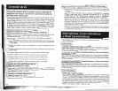
SHARING/EQUALIZE BATTERY CHARGE
LOAi
Using
on
thc
the
'1
lasmall tool, setthemLoadSharing' Configuration DIP Switches,
#1
and#2of Group B (located
3
front panel of your APS; see Diagram 1, p. 32). DIP Switch #3, Group B should be kept in
JP'
position when you are not equalizing your batteries' charges. DIP Switch #4, Group B
has no function.
Load Sharing
(DIP Switches #1, Group B
&
#2, Group B)
Your APS features a high-output battery charger that can draw a significant amount of power
from your line power source when charging at its
maximum rate. If an APS is supplying its full
AC power rating to its
connected load at the same time as it is charging, it could trip its line source
circuit breaker. Tripping this breaker will cut off AC power to your load and stop battery charging.
--
-
To reduce thechanceof tripping this breaker, select APS models may be set to automatically
limit their charger output to keep the sum of their AC load and charger power within their circuit
breakers' rating.
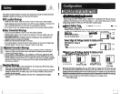
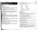
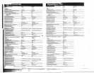
This charger limiting function has four settings, allowing you to choose less charger limiting
for APS configurations with higher rated breakers. The figures below show how to set your
DIP Switches to select how heavy a load can be placed on your APS before charger limiting
begins.
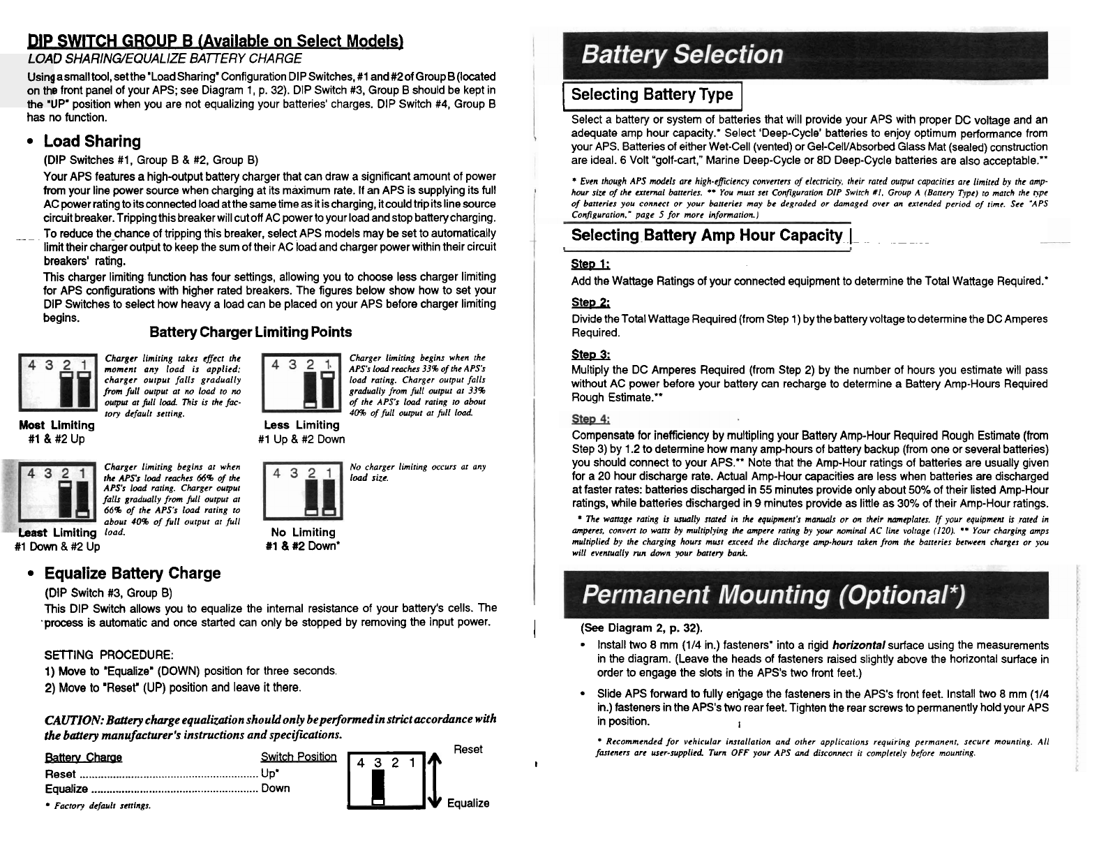
Battery Charger
Limiting Points
Chargcr limiring rakes cffecr rhe
momcnr any load is applied:
chargcr ourpur falls gradually
from
full ourpur ar
no
load ro
no
ourpvl ar full load
Thir
is rhe fa-
tory default scrring.
Most
Limiting
#1 & #2 Up
Charger limiring begins when rhe
APSs load reaches 33% of rhe APSk
load raring. Charger ourpur falls
gradually from full ourpur
or 33%
of rhc
APSs load raring ro abour
40%
of full ourpur or full load
Less Limiting
#1 Up
&
#2 Down
Charger limiting begins ar when
No charger limiring occurs ar any
rhc APSs load reaches
66%
of rhc
load size.
APSs load raring. Charger ourpur
falls gradually
from
full ourpur or
66%
of rhc APSk load raring to
abour
40%
of full ourpur or full
warL Limiting
load.
No
Limiting
#1
Down
 Up
#1
&
#2 Down'
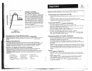
Equalize Battery Charge
(DIP Switch
#3,
Group B)
This DIP Switch allows you to equalize the internal resistance of your battery's cells. The
.process is automatic and once started can only be stopped by removing the input power.
SElTiNG PROCEDURE:
1) Move to 'Equalize' (DOWN) position for three seconds.
2)
Move to 'Reset' (UP) position and leave it there.
CAUTION:
Battery charge equalization should only beperformed in strict accordance with
the battery manufacturer's instructions and
speciflations.
l%m@amW
Switch Positio"1 Reset
Reset
.............................
. .
...
..
...
....
...
....
.....
... .
UP'
Equalize
......................................................
Down
Factory defaulr senings.
Equalize
I
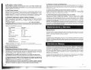
Selecting Battery Type
I
I
I
Select a battery or system of batteries that will provide your APS with proper DC voltage and an
adequate amp hour capacity: Select 'Deep-Cycle' batteries to enjoy optimum performance from
your APS. Batteries of either Wet-Cell (vented) or
Gel-CelVAbsorbed Glass Mat (sealed) construction
are ideal.
6
Volt "golf-cart," Marine Deep-Cycle or 8D Deep-Cycle batteries are also acceptable."
Even rhough APS models arc high-eficiency converrcrs of elecrriciry, their rared ourpur capaciries arc limircd
by
rhe amp-
hour
size of rhc exrcrnal bancries.
**
You musr scr Configurarion DIP Swirch
#I.
Group
A
(Bancry Type) ro march rhr r?pe
of barrcries you connecr or your hrrcrics may bc degraded or damaged over an cxrcndcd period of rime. See 'APS
Configurarion.' page
5
for more infomarion.)
Selecting~Battery
Amp
Hour Capacity
-
~-
~
-p
-~
--
SteD
1;
Add the Wattage Ratings of your connected equipment to determine the Total Wattage Required.'
Stel,
2:
Divide theTotal Wattage Required (from Step 1) by the battery voltage to determine the DC Amperes
Required.
SkfGk
Multiply the DC Amperes Required (from Step 2) by the number of hours you estimate will pass
without AC power before your battery can recharge to determine a Battery Amp-Hours Required
Rough Estimate."
Compensate for inefficiency by multipling your Battery Amp-Hour Required Rough Estimate (from
Step 3) by 1.2 to determine how many amp-hours of battery backup (from one or several batteries)
you should connect to your APS." Note that the Amp-Hour ratings of batteries are usually given
for a 20 hour discharge rate. Actual Amp-Hour capacities are less when batteries are discharged
at faster rates: batteries discharged in
55 minutes provide only about
50%
of their listed Amp-Hour
ratings, while batteries discharged in
9
minutes provide as little as 30% of their Amp-Hour ratings.
Thc wanage raring
u
uually stared in rhc rquipmenr's manuals or on rhrir namcplarcs.
If
your equipmcnr
is
rared in
ampercs, conven ro warrs by mulriplying rhc ampere raring by your ~minal AC line voltage (120).
**
Your charging amps
multiplied by
rhe charging hours musr crcecd rhc discharge amp-hours rakcn from rhc barrcrics bcwcen charges or you
will
evcnrually run down your bancry bank.
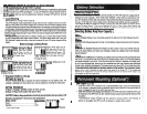
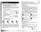
I
(See
Diagram
2,
p.
32).
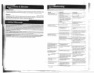
lnstall two 8 mm (114 in.) fasteners' into a rigid
horizontal
surface using the measurements
in the diagram. (Leave the heads of fasteners raised slightly above the horizontal surface in
order to engage the slots in the APS's two front feet.)
Slide APS forward to fully engage the fasteners in the APS's front feet. Install two 8 mm (114
in.) fasteners in the APS's two rearfeet. Tighten the rear screws to permanently hold your APS
in position.
I
Rccommcnded for
vehicular
insrallarion and orher applicarions requiring pcrmanenr, secure mounring. All
fmencrs arc user-supplied Turn
OFF
your APS and disconnccr ir complcrcly before mounring.
I