


9
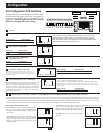
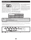
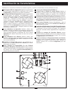
Series Connection
mustmatch the number of batteries multiplied by their voltage.
connected
Contact Tripp Lite technical support for assistance with additional parallel, series or series/parallel connections.
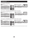
1
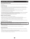
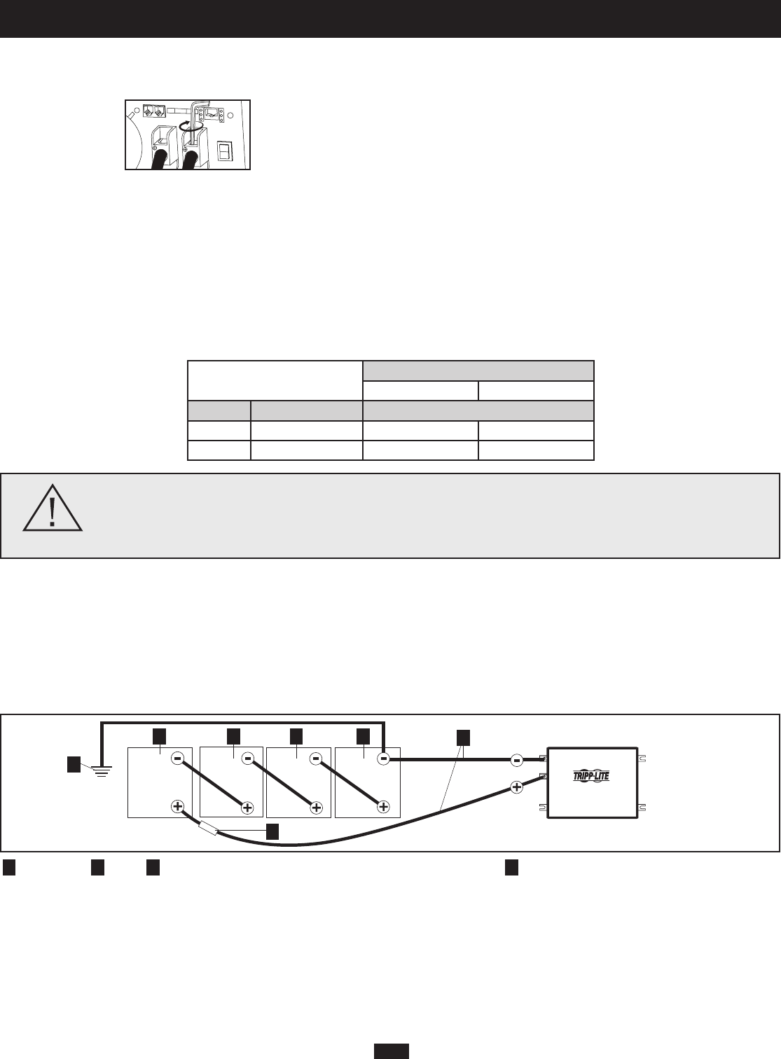
EarthGround
2
Battery
3
UL-ListedFuse&FuseBlock(mountedwithin450mmofthebattery)
4
LargeDiameterCabling,Maximum9.3mmdiameter
(2/0AWG)toFitTerminals
48V Inverter/Charger
12 Volts
12 Volts 12 Volts 12 Volts
Multiple Battery Connection (Series)
Figure below illustrates 12V batteries with a 48V Inverter/Charger.
1
2 2 2 2
4
3
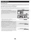
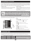
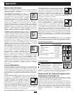
Battery Connection
• Connect DC Wiring: Though your
Inverter/Charger is a
high -effici ency
converter of
electricity, its rated
output capacity is
limited by the length
and gauge of the
cabling running from the battery to the unit.
Use the shortest length and largest diameter
Input terminals. Shorter and heavier gauge
cabling reduces DC voltage drop and allows
Inverter/Charger is capable of delivering
continuous wattage output for brief periods
used when continuously operating heavy
draw equipment under these conditions.
Tighten your Inverter/Charger and battery
meters of torque to create an
efficient connection and to prevent
Insufficient tightening of the terminals could
void your warranty. See table below for
recommendedcablesizingchart.
• Connect Ground:
Lug to earth
ground. See the Feature Identification
Lug on your
specific Inverter/Charger model. All
installations must comply with national and
local codes and ordinances.
• Connect Fuse: Tripp Lite recommends
that you connect your Inverter/Charger’s
positive DC Terminal directly to a fuse and
Inverter/Charger's nameplate. See diagrams
below for proper fuse placement.
ConnectyourInverter/Chargertoyourbatteriesusingthefollowingprocedures:
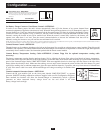
WARNING! • Failure to properly ground your Inverter/Charger to earth ground may result in a lethal
electrical shock hazard.
• Never attempt to operate your Inverter/Charger by connecting it directly to output from an alternator
rather than a battery or battery bank.
• Observe proper polarity with all DC connections.
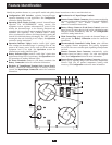
DC Connectors
MaximumRecommendedDCCableLength
Wire Diameter (Gauge)
8.3 mm (0 AWG) 9.3 mm (2/0 AWG)
V
DC
Output Power Maximum Distance from Battery to Unit
24V 3000W 13 m (42 ft) 16 m (52 ft)
48V 6000W Do not use 32 m (105 ft)