


3
Quick Installation
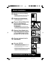
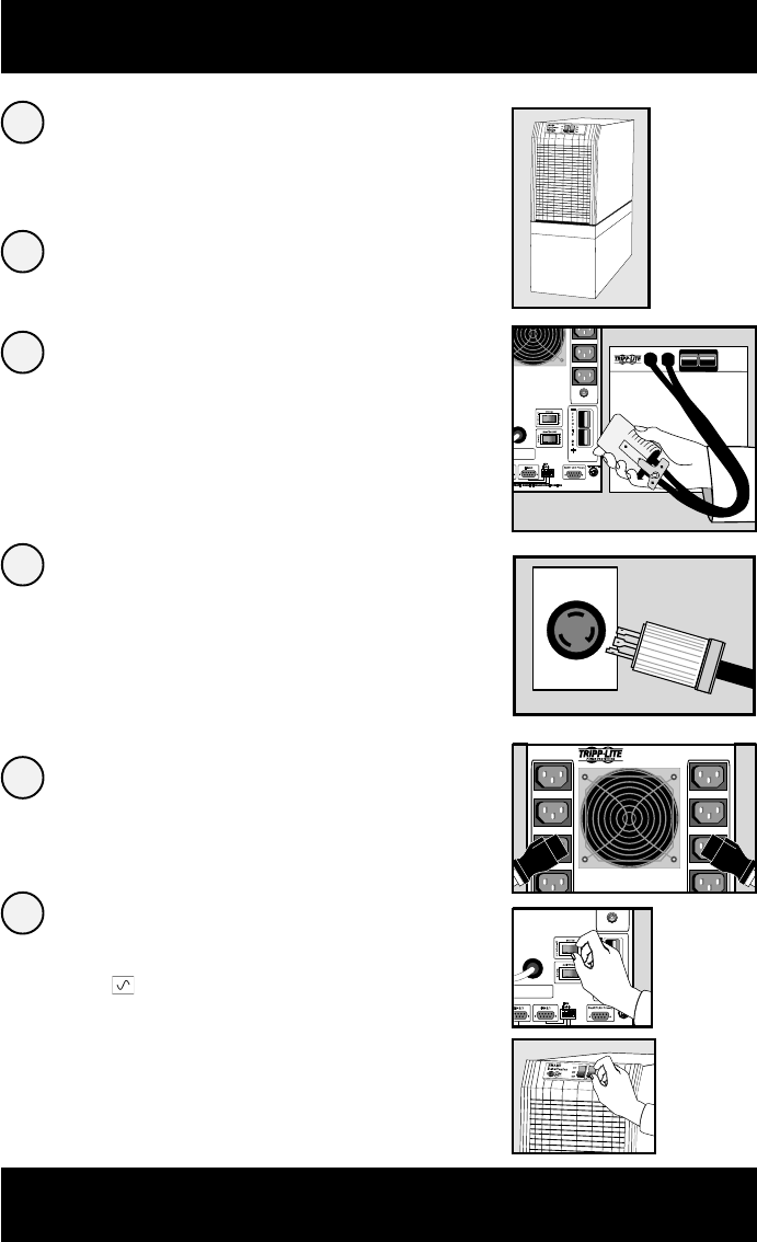
Position your External Battery
Pack(s).
• If positioning multiple Battery Packs, place them side
by side or stack them no more than three high.
Position your Power Module.
• The Module may be stacked on top of your Battery
Packs or placed beside them.
Plug your External Battery Pack
into your Power Module's
External Battery Connector on
its back panel.
• For multiple Battery Packs, connect the first to the
Power Module, then daisy-chain the others: connect the
second to the first, the third to the second, and so on.
Plug your Power Module into a
L6-30 single-phase AC outlet on
a 30-amp dedicated circuit that
provides 220V to 240V at 50 Hz.
Plug your equipment into the
Power Module.
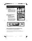
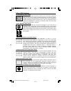
Turn your UPS ON.
• Set the System Switch on the UPS's back panel to the
“ENABLE” (RIGHT) position. (Figure 1a)
This switch activates the battery charger and microprocessor.
The “ ” light will flash until you engage the ON/Standby
Switch to activate the “ON” mode.
• Engage the momentary ON/Standby Switch on the UPS's
front panel and release it to activate the “ON” mode and
supply power to the UPS receptacles. (Figure 2b)
2
1
3
Communications on Next Page...
4
5
6
0
0VA 4500W
M
50/60HZ 5000VA 3700W
50HZ 5000VA 3700W
CAUTION: DO NOT UNPLUG WHILE
OPERATING OR ARCING WILL OCCUR
36VDC 175 AMPS MAX
BRANCH CIRCUIT #1
230VAC 10AMPS
5
0/60HZ 5000VA 4500W
3
0VAC NOM 50/60HZ 5000VA 3700W
0
VAC NOM 50HZ 5000VA 3700W
CAUTION: DO NOT UNPLUG WHILE
OPERATING OR ARCING WILL OCCUR
36VDC 175 AMPS MAX
BRANCH CIRCUIT #1
230VAC 10AMPS
1a.
Back panel
2b.
Front panel
9905251 230V SmartPro Datacenter OM.p65 8/8/00, 2:02 PM3