


5
Basic Operation
Switches
System Switch (Middle Back Panel)
This switch activates the UPS's battery charger and intelligent
microprocessor. ALWAYS leave it in the “ENABLE” (RIGHT)
position when your UPS is plugged in. Only set the switch to
“DISABLE” (LEFT) to reduce battery drain when you unplug your
UPS for storage or shipping.
Note: When this switch is on "ENABLE", the “ ” light will flash until you engage the ON/
Standby Switch to turn power ON at the UPS receptacles.
ON/Standby Switch (Front Panel)
This momentary switch on the front panel controls power to the
UPS receptacles. Engage it momentarily and release it to toggle
between the “ON” mode (power ON at the UPS receptacles) and
“Standby” mode (power OFF at the UPS receptacles).
Mute/Test Switch (Front Panel)
Use this momentary switch on the front panel to do two things:
Silence the UPS On Battery alarm
Engage this switch and release it to silence the UPS On Battery
alarm, a series of short beeps that sounds intermittantly when
the UPS is providing AC power from battery. Note: when the
battery is nearly depleted, the Low Battery alarm, a continuous
beep that cannot be silenced, will alert you to immediately shut
down connected equipment.
Test your UPS’s battery charge
Leave your connected equipment ON. With your UPS plugged in
and completely turned ON, engage this switch; hold it there for
5 seconds and release it. You will hear a series of short beeps as
the UPS momentarily switches to battery to test its charge. The
“
” light will turn ON and the alarm (a long, continuous beep)
will sound if your UPS fails a self-test and/or the UPS battery is
less than fully charged. If this occurs, let the UPS charge for 12
hours and perform a second self-test. If the light continues to
stay on, contact Tripp Lite for service. CAUTION: Do not unplug
your UPS to test its batteries. This will remove safe electrical
grounding and may introduce a damaging surge into your network
connections.
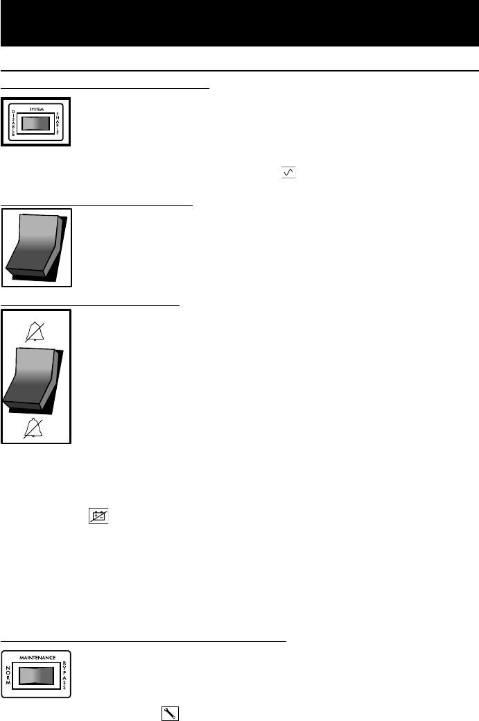
Maintenance Bypass Switch (Middle Rear Panel)
This switch, used during hot swap battery replacement, should be
left in the “NORMAL” (LEFT) position during ordinary operation.
Set this switch to “BYPASS” (RIGHT) to connect or disconnect
external battery packs while the UPS is plugged in and supporting
a load. The “ ” light on the front panel will light to indicate that
battery backup protection is not available until this switch is
returned to the "NORMAL" (LEFT) position.
—
O
9905251 230V SmartPro Datacenter OM.p65 8/8/00, 2:02 PM5