


7
3.7 Electrical Connection
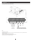
3.8 Battery Charger Electrical Connection (Select Models)
3.9 Final Electrical Check
3. Battery Cabinet Installation
(
continued
)
The battery cabinet should be connected to the load through a DC disconnect switch or a DC circuit breaker. This allows the •
battery to be disconnected from the load and charger for maintenance and/or repair.
The DC rated fuses and DC molded case circuit breakers are UL-listed for branch circuit protection. If replacement is •
required, UL-listed components with the same voltage and current rating must be used.
The size of the load connection cables must consider maximum allowable voltage drop as well as the cables’ continuous •
ampere capacity and anticipated ampere discharge rate of the individual battery cabinet. A maximum voltage drop of 1.5
VDC in the load connection cables is recommended.
Refer to all applicable local, state and national codes (including NEC) for appropriate cable size and ratings.•
External circuit protection devices (fuses or circuit breakers) must consider the discharge rate of the battery, the wiring to be •
protected and the DC short circuit current of the battery.
When the battery cabinets are connected in parallel, they should be joined together with separate output cables of equal total •
length at a junction box or other suitable distribution panel.
If the battery cabinet includes an integrated battery charger (“C” models only), the charger input must be connected to an AC •
supply circuit separate from the UPS system.
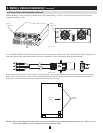
Remove the battery cabinet’s access panels to access internal components. Use a digital voltmeter when voltage 1.
measurements are required.
Determine if the battery has been inadvertently grounded by measuring the voltage between the battery cabinet grounding lug 2.
and the positive load connection point within the cabinet. This voltage should measure 0 (zero) VDC. If the measured voltage
is not zero, determine the cause and correct before proceeding.
Place the internal circuit breaker in an open position during the connection of the output cables to prevent damage if the 3.
cables are accidentally shorted.
The top and sides of the battery cabinet include knockouts for load connection cable entry. Punch out the appropriate 4.
knockout and connect the conduit or cable bushing.
The output terminal blocks, fuse blocks, disconnect switches and circuit breakers will accommodate cables up to 500 MCM 5.
(500 kcmil).
Feed the positive and negative cable from the open external disconnect switch through the conduit/cable bushing and connect 6.
to the respective output terminals inside the battery cabinet.
Reinstall any internal cabinet fuses that were removed in step 2 (above). All disconnect switches or circuit breakers must 7.
remain in the open position during reinstallation of the fuses.
Connect an appropriate equipment grounding cable to the grounding lug mounted in the top of the battery cabinet or to the 8.
grounding pad on the rear leg of the battery cabinet.
Select battery cabinets (“C” models only) include an integrated battery charger. The charger includes fusing for 120 VAC 1.
input. Refer to Section 6-5 for a terminal block diagram and additional battery charger information.
Set the battery cabinet input voltage to 120 VAC by jumpering these terminals: 2 and 3, 3 and 4, 5 and 6.2.
Connect charger terminals 7 and 8 to a 30-amp, 120 VAC, 60 Hz power source. 3. Warning: Do not connect the battery
charger to the UPS system output. The battery charger requires a separate AC supply circuit.
Before closing any connecting circuit breaker or disconnect switch, complete these verication steps:
Verify that the battery cabinet output voltage is correct.1.
If battery cabinets will be operated in parallel, verify that the individual system output voltages match within 2 VDC.2.
Verify that the voltage measured between either output terminal and the battery cabinet ground is zero.3.
If any of the above verication steps shows an irregularity, determine and correct the cause before proceeding.4.
DANGER! LETHAL HIGH VOLTAGE HAZARD!
All wiring should be performed by a qualied electrician, in accordance with the warnings in this manual
and all applicable electrical and safety codes. Incorrect wiring may cause serious personal injury and
property damage.