


8
Features (Rear Panel)
continued
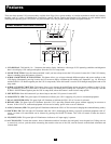
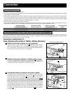
Power Module Feature Description
(6kVA and 10kVA models)
1. Output Terminal Block: Use these terminals to connect your power module to your equipment or to the transformer module. Unscrew
and remove the cover over the block for access.
2. Input Terminal Block: Use these terminals to connect your power module to utility power or to the transformer module. Unscrew and
remove the cover over the block for access.
3. External Battery Connector: Use this to connect one or more Tripp Lite battery modules to the power module. Remove the cover for
access. The power module will not start without a connection to a charged battery module. Refer to the battery module owner’s manual
for connection instructions and safety warnings.
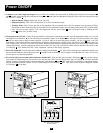
4. AC Input Breaker: One double-pole circuit breaker controls input power to the power module.
5. AC Output Breaker: One double-pole circuit breaker controls output power from the power module.
6. Exhaust Fan: This cools and ventilates the inside of the power module.
7. Accessory Slot: Remove the small cover panel to install optional accessories to remotely control and monitor your UPS system. Visit
Tripp Lite on the Web (www.tripplite.com) to learn about available SNMP, network management and connectivity products that may be
installed in this slot.
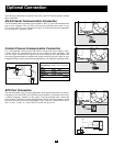
8. EPO (Emergency Power Off) Port: The power module features an EPO port that may be used to connect the power module to a contact
closure switch to enable emergency power off. See “Optional Connection” section for details.
9. RS-232 Communication Port: This female DB9 serial port may be used to connect your UPS to a workstation or server. It uses RS-232
protocol to communicate with a connected computer. It is used with Tripp Lite software and the included serial cable to monitor and
manage the UPS remotely over a network and to automatically save open files and shut down equipment during a blackout. See
“Optional Connection” for details.
10. Dry Contact Interface Port: This female DB9 port sends contact-closure signals to indicate line-fail and low-battery status. See
“Optional Connection” for details.
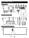
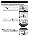
Isolation Transformer Module Feature Description
(6kVA and 10kVA models)
11. Utility Input Terminal Block: Use these terminals to connect your transformer module to utility power. Unscrew and remove the cover
over the block for access.
12. Equipment Output Terminal Block: Use these terminals to connect your equipment to the transformer module. Unscrew and remove
the cover over the block for access.
13. Cable for Power Module Connection (6kVA models only): Connects the transformer module to the power module’s input/output after
the power module’s terminal blocks have been removed. See “Connection” section for details.
14 Hardwire Terminal Block for Power Module Connection (10kVA models only): Use these terminals to connect the transformer mod-
ule to the power module’s input and output terminal blocks. See “Connection” section for details.
15. Overtemperature Reset Breaker: This circuit breaker trips if the unit’s temperature climbs too high.
16. AC to UPS Breaker: One double-pole circuit breaker controls the transformer module’s power output to the UPS.
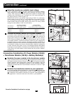
17. Output Breaker: One triple-pole circuit breaker controls the transformer module’s power output to connected equipment.
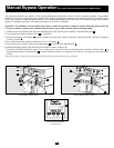
18. Manual Bypass Switch: This red and yellow dial is used to circumvent the power module while still supporting connected equipment
when performing power module maintenance. While this switch is on BYPASS, connected equipment will receive filtered AC mains
power from the transformer module, but the equipment will not receive battery power in the event of a blackout. See “Manual Bypass
Operation” section for complete bypass procedure.
WARNING! For qualified service personnel only. Failure to follow the bypass procedure completely will not adequately power
down the UPS power module, resulting in the continued risk of death or injury from potential contact with high voltage.
19. Input Voltage Select Switch: Use this switch to set the transformer module's input voltage (either 200V AC, 208V AC or 240V AC).
See “Connection” section for details.
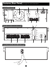
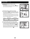
Battery Module Feature Description
(6kVA and 10kVA models)
20. Input Connector: Use this connector to daisy chain additional battery modules onto the first. Remove the cover panel for access. Refer
to the battery module owner’s manual for connection instructions and safety warnings.
21. Output Cable: Use this cable to connect the battery module to the power module or to another battery module. The power module will not start
without a connection to a charged battery module. Refer to the battery module owner’s manual for connection instructions and safety
warnings.