


9
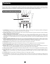
There are three separate UPS system modules available from Tripp Lite (a power module and a battery module, which are required in all
applications, and an isolation transformer module) used in a variety of combinations. Follow the connection procedure below which matches
the combination of modules which you plan on installing.
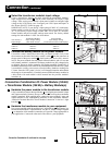
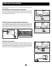
Connection Combination #1:
Power Module (either 6kVA or 10kVA) + Battery Module(s)
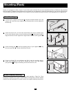
Hardwire the power module to your equipment.
Using a screwdriver, remove the top of the box covering the power module’s
input and output terminals. Pass a user-supplied cable through the terminal
box’s left knockout and connect it to the power module’s output terminals.
Connect the other end of the cable to your equipment.
Hardwire the power module to a utility power source.
Pass a user-supplied cable through the box’s right knockout and connect it
to the power module’s input terminals. Replace the top of the terminal box.
Connect the other end of the cable to a utility power source.
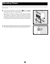
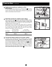
Connect the battery module to the power module.
Consult the owner’s manual that came with your battery module. Fully insert
the connector on the end of the battery module’s cable into the connector
on the rear panel of the power module . Small sparks may occur; this is
normal. NOTE: the power module does not contain internal batteries and will not
start until a battery module is connected. The battery modules are fully charged
prior to shipping. However, before expecting full backup capability (particularly
if the battery module has been stored for an extended period) after the UPS system
is connected to a utility power source, allow the battery module to recharge for
12 hours. Once the UPS system is in use, it will charge the batteries and maintain
the charge level automatically. If needed, connect additional battery modules
in a daisy-chain with each module’s cable inserted into the previous module’s
connector .
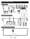
F
E
D
C
B
A
1
2
2
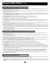
Connection
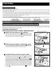
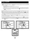
• Wiring must be done by a qualified electrician.
• The UPS power module may be installed on its own or connected to an isolation transformer module. Both applications require the power module
to be connected to a battery module.
• When making wiring connections, observe the cable connection regulations appropriate to your area [e.g. National Electrical Code (NEC)
in the U.S.] at all times. Be sure to install an easily accessible disconnect switch in your installation wiring so you may cut off the UPS’s
AC input during fires and other emergencies. Ensure that cables are fitted with cable sleeves and are secured by connector clamps. Tighten
connections with a torque of not less than 24-28 inch-pounds (2.7-3.2 NM).
• Make sure that your equipment is properly grounded.
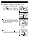
• Using cables of improper size may damage your equipment and cause fire hazards. Choose appropriate cabling and protection circuits to
make wiring connections (Ground conductors must be the same size and type as the power conductors used):
RATED INPUT CURRENT RATED OUTPUT CURRENT RATED OUTPUT CURRENT OUTPUT PROTECTION
200 - 240 (1Ø, 2-Wire + PE) 200 - 240V (1Ø, 2-Wire + PE) 120V (1Ø, 2-Wire + PE) CIRCUIT
6kVA Models 30A 8 AWG (10mm
2
) 30A 8 AWG (10mm
2
) 2 × 30A 8 AWG (10mm
2
) 30A
10kVA Models 50A 6 AWG (16mm
2
) 50A 6 AWG (16mm
2
) 2 × 50A 6 AWG (16mm
2
) 63A
Connecting Modules to Each Other and to Utility Power and Equipment
Hardwiring Cautions
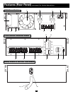
3
3
A
B
C
D
E
F
1
6kVA Power Module Shown