


15
Manual Bypass Procedure
WARNING! For qualified service personnel only. Failure to follow the bypass procedure completely will not adequately power down
the UPS, resulting in the continued risk of death or injury from potential contact with high voltage. The UPS is extremely heavy. This
procedure requires several people to perform.
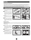
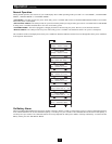
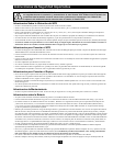
The UPS system includes an independent, detachable PDU with a bypass switch. This switch allows qualified service personnel to remove the
detachable PDU from the power module for maintenance, repair or replacement without disrupting power to connected loads. While this
switch is set to “BYPASS”, connected equipment will receive unfiltered AC mains power, but the equipment will not receive battery power in
the event of a blackout.
Note: An optional hardwire output detachable PDU is also available. Contact Tripp Lite for details.
I/P BYPASS
BATTERY AC/DC DC/AC O/P
OFFON
MUTE SELECT
SETUP
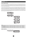
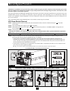
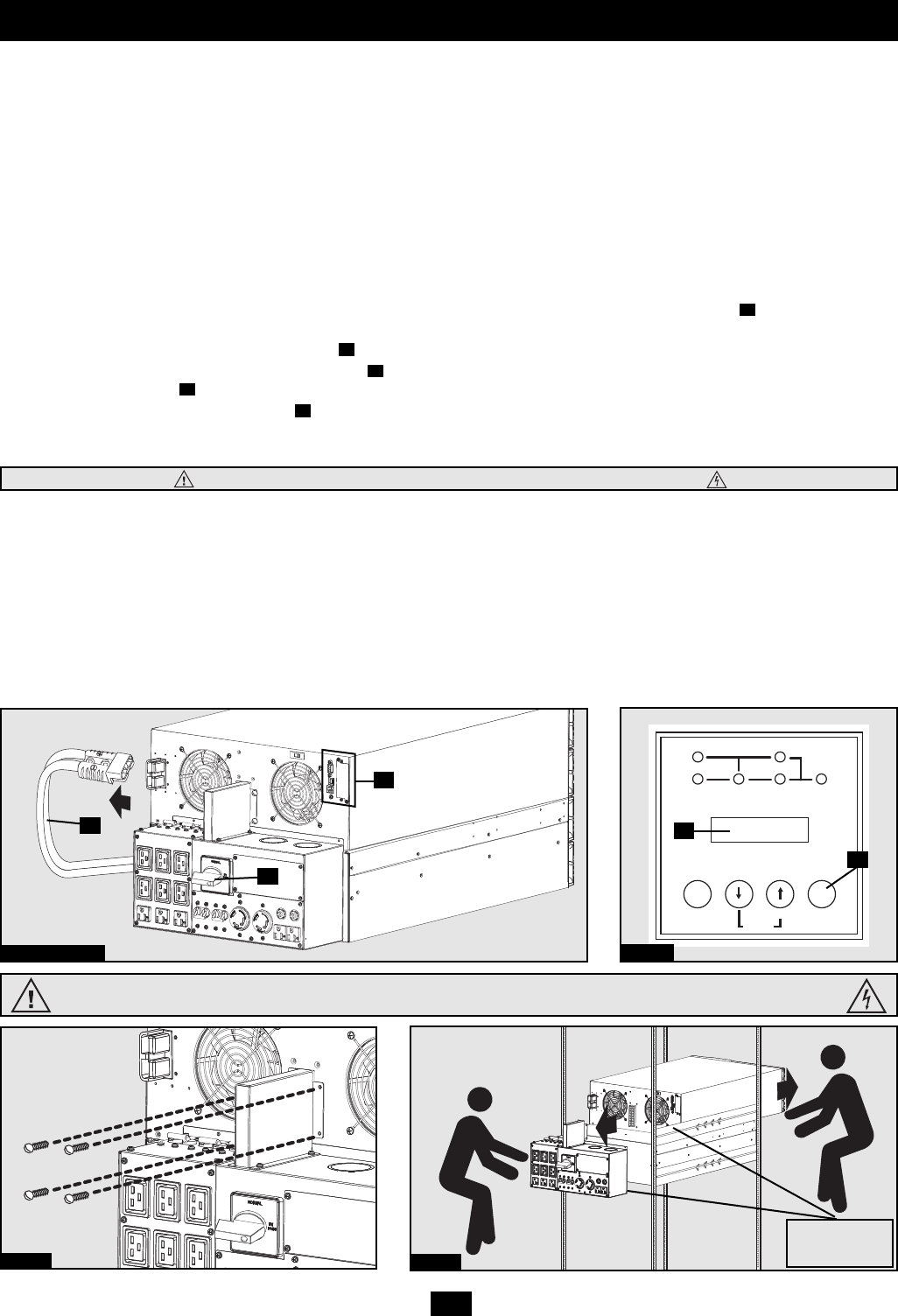
UPS Power Module Removal
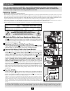
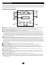
STEP 1. Disable PowerAlert Software and disconnect all communication cable(s) from the communication port(s) on the UPS
power module.
STEP 2. Turn the detachable PDU's Bypass Switch to “BYPASS”.
STEP 3. If the UPS is powered, press the “OFF” button until you hear a beep and see a “STANDBY MODE” message shown in
the LCD Display .
STEP 4. Disconnect the battery power cable from the UPS power module.
The UPS power module is now safely powered down and it can be detached from the PDU to perform maintenance/replacement.
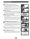
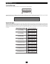
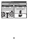
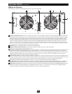
STEP 5. Remove the screws that hold the detachable PDU to the power module.
STEP 6. Using several assistants at each end, carefully pull the detachable PDU away from the power module. During this process,
ensure that each section is properly supported after they are separated.
• If the sections are detached in a rackmount application, ensure that each section remains adequately supported by the
rackmount rails. Remove the rackmounting hardware from the front panel of the UPS; slide the power module forward, and
remove. The PDU will remain supported on the rackmount rails. Care should be taken in this process because the PDU will
not be secured to the rack with hardware of any kind.
• If the sections are detached in a tower application, ensure that the PDU is supported by the UPS's tower feet. Adjust the tower
feet so they are as close together as possible.
Warning: Use extreme caution when handling the PDU. Do not allow the contacts to touch any surface.
To reattach the PDU, reverse the process listed above.
E
D
C
B
A
Steps 1, 2 & 4
Step 3
E
B
A
D
C
Step 5
Step 6
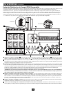
WARNING! High Voltage! Risk of electrical shock! SEE NEXT PAGE.
See warning
statements on
next page!
WARNING! High Voltage! Risk of electrical shock! SEE NEXT PAGE.