


4
Features (continued)
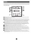
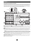
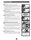
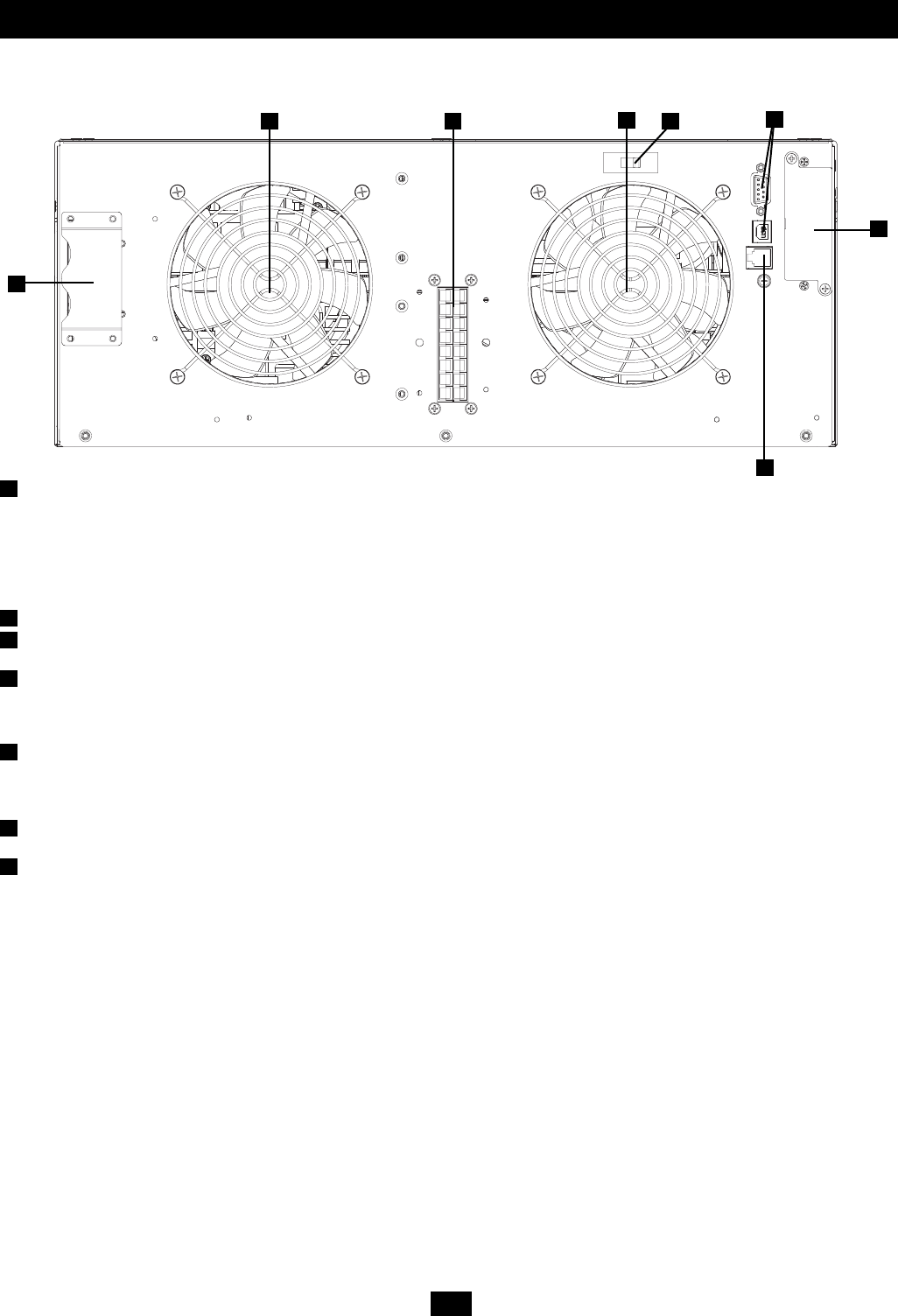
Power Module
This 4U module houses the UPS system's power and control components.
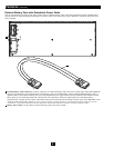
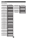
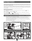
External Battery Connector: Use this connector to attach one or more Tripp Lite external battery packs to the power module. Remove
the retention bracket for access. The power module will not start without a connection to a charged, compatible battery pack. Check to
ensure that the external battery pack you are connecting matches the voltage listed next to the battery connector. Small sparks may result
during battery connection; this is normal. Do not connect or disconnect battery packs while the UPS is running on battery power (the
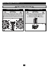
“BATTERY” LED will be lit on the control panel). Warning: Always use the connector retention brackets to secure the battery pack
connection (see the “Connection” section for instructions). Do not operate the UPS system without the connector retention brackets in
place. Refer to the battery pack owner's manual for additional connection instructions and safety warnings.
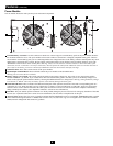
Ventilation Fans: These fans cool the interior of the power module.
Input/Output Terminal Block: These terminals connect the power module to the detachable PDU.
Warning: Do not contact the live terminals.
Battery Charge Level Switch: This switch controls the UPS system's battery charge rate. The switch is set to the left (the position
labeled “NORMAL”) by default. If you connect more than one external battery pack to the UPS system, set the Battery Charge Level
Switch to the right (the position labeled “HIGH”), allowing the additional batteries to charge faster. Warning: Setting the Battery Charge
Level Switch to “HIGH” when only one battery pack is connected may damage the battery pack.
Serial and USB Ports: These serial (RS-232 DB9) and USB ports enable optional connection of the UPS to corresponding ports on a
workstation or server. When the UPS system is connected to a computer via the included serial or USB cable, Tripp Lite's PowerAlert
Software can be used to monitor and control the UPS system. PowerAlert can also save files and shut down computers automatically
during extended power failures. (See “Optional Connection” section for more information.)
EPO Port: This port enables optional connection to a facility's EPO (Emergency Power Off) circuit for emergency shutdown of the UPS
inverter. (See “Optional Connection” section for more information.) Do not connect a telephone line to this port.
Accessory Slot: Remove the slot's cover to install an optional internal SNMP/Web accessory card (Model: SNMPWEBCARD) to enable
remote UPS monitoring and control via SNMP, Web or telnet. Call (773) 869-1234 or go to www.tripplite.com to learn about available
SNMP, network management and connectivity products.
1
2
3
4
5
6
7
1
2 3
2
4
5
6
7