


20
1
5
9
3
7
11
2
6
10
4
8
12
13
14
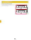
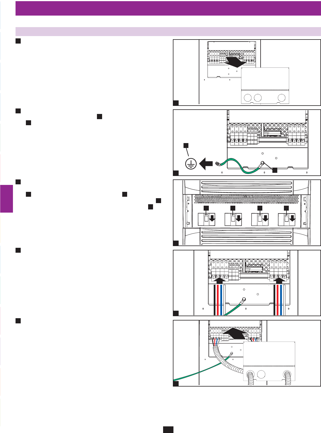
7 – Wiring (continued)
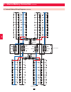
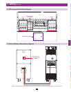
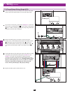
7-7 AC Input/Output Wiring (Single UPS)
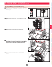
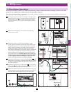
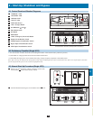
After de-energizing all input and output (AC and DC) of the UPS •
system, remove the terminal block cover from the UPS system.
If you did not connect the ground cable in •
Section 7-6, connect the
UPS system’s grounding terminal
A
to your facility’s earth ground
B
with a 4 AWG (5.189 mm) ground cable. Keep the ground cable
connected at all times after installation.
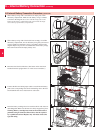
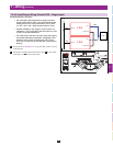
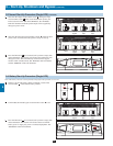
Remove the UPS system’s front bezel to expose the circuit •
breakers. First, confirm that the main input circuit breaker switch
A
and the bypass input circuit breaker switch
B
are both off.
Second, confirm that the manual bypass circuit breaker switch
C
is off. Third, confirm that the output circuit breaker switch
D
is
off.
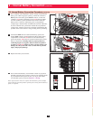
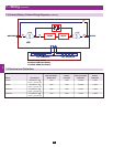
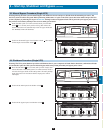
Confirm the phase of each cable, then connect the cables according •
to the UPS system terminal block diagram in
Section 7-3. See
Section 7-5 for cable size requirements. Cabling should be
protected by flexible conduit and routed through the appropriate
knockouts in the terminal block cover. Warning: Observe proper
phase by connecting R to R, S to S, T to T and N to N. Failure
to observe proper phase will damage the UPS system and
create a risk of personal injury and property damage.
Replace the UPS system’s terminal block cover.•
1
1
2
4
5
2
3
3
4
5
B
+
N
–
R S T
N
R S T
N
D B AC
A