


4
Connection
In order to make connections between 2 UPS systems in parallel, two 6kVA UPS systems, the primary detachable PDU module and the secondary
PDU module will be needed.
1
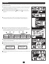
Being sure that all switches are off and all units are powered down, refer back to the
“Mounting” section of the manual. First, mount the UPS systems and then the primary and
secondary parallel PDUs.
2
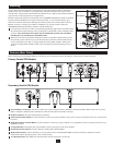
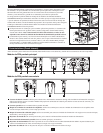
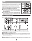
Originating from the secondary PDU interconnect port
A
, connect the parallel power
interconnect cable
B
to the primary PDU
C
as seen in diagram 2.
3
Connect the 2 parallel cables. Both will originate from the primary parallel PDU with 1
connecting to UPS system 1 and the other to UPS system 2. (Refer to diagram 3.)
4
Connect the hardwired input and output AC power connections (L1, L2 and Ground wires) to
the primary PDU, according to the markings on the connectors. The AC input wiring attaches
to the facility’s AC source while the AC output wiring connects to the intended equipment.
Model Input Voltage
Maximum Rated
Input Current
Maximum Rated
Output Current
Typical
Wire Size
SUPDMB12KHW 200~240V (L-N) 60A 60A 8mm
2
5
With all switches in the OFF position, turn ON both the input breakers on the primary and
secondary PDUs. Leave switches for the output breakers in the OFF position.
6
Power ON UPS system 1, being sure that the output breakers are OFF.
7
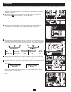
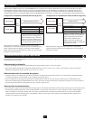
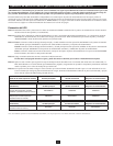
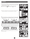
After UPS system 1 start-up is complete, power ON UPS system 2. The UPS systems will self
detect the Parallel Mode and show the following screen shots for the primary and secondary
UPS systems:
When the unit is in Parallel Mode UPS system 1 will display “Parallel: Master” and UPS
system 2 will display “Parallel: Slave”.
8
Once Parallel Mode is detected, turn on both output breakers for the primary and secondary
PDUs.
2
3
4
5
8
PARALLEL: MASTER
V00 CV01
PARALLEL: SLAVE
V00 CV01
A
B
C