


5
Manual Bypass Operation (for UPS maintenance or replacement)
WARNING! For qualified service personnel only. Failure to follow the bypass procedure completely will not adequately power down
the UPS, resulting in the continued risk of death or injury from potential contact with high voltage. The UPS and detachable PDU are
extremely heavy. This procedure requires several people to perform.
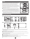
The UPS system includes an independent, detachable PDU with a Maintenance Breaker Switch. This switch allows qualified service personnel
to remove the detachable PDU from the UPS for routine maintenance without disrupting power to connected loads. While this switch is set to
“BYPASS”, connected equipment will receive unfiltered AC mains power. But the equipment will not receive battery power in the event of a
blackout.
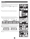
UPS Removal
STEP 1. Disable PowerAlert and disconnect the SNMP or serial USB communication cables from the communication ports on the UPS. Do NOT
remove the parallel cable (if installed) at this point.
STEP 2. First, determine your maintenance status (i.e. which UPS system requires maintenance and whether you are in Redundancy or Power
Mode). Press UPS’s “OFF” button, if the UPS is powered, until you hear a beep and see a “BYPASS MODE” message shown in its LCD
Display.
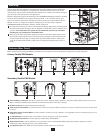
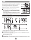
STEP 3. Part A: When the output is coming from the Primary UPS and the Secondary UPS needs repair, set the Primary PDU’s Input/Output
Breakers ON, the Secondary PDU’s Input/Output Breakers OFF and the Maintenance Breaker OFF.
Part B: When the output is coming from the Secondary UPS and the Primary UPS needs repair, set the Primary PDU’s Input/Output
Breakers OFF, the Secondary PDU’s Input/Output Breakers ON and the Maintenance Breaker OFF.
Part C: When the output is in Bypass, set Maintenance Breaker Switch to the ON position. At this point, remove the parallel cable from the
UPS.
STEP 4. If an external battery module is connected to the UPS, disconnect it from the UPS.
The UPS is now safely powered down and it can be detached from the PDU to perform maintenance/replacement.
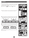
STEP 5. Remove the four screws that secure the front mounting ears of your UPS to the rack. With the PDU still attached, move the UPS system
and PDU forward in the rack slightly (approximately 4 inches), being sure that both components remain adequately supported by the UPS’s
rackmount support rails.
STEP 6. At the rear of the UPS, remove the four screws that hold the detachable PDU to the UPS that is being serviced. With an assistant holding
the front of the UPS in place, carefully detach the PDU from the rear of the UPS and rest it on the UPS support rails. Remove the UPS from
the rack.
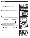
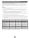
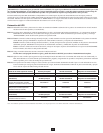
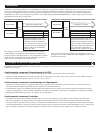
Output Status (Normal Operation)
Primary PDU Input/Output
Breakers
Secondary PDU Input/Output
Breakers Maintenance Breaker*
Output coming from both UPS systems. ON ON OFF
Output Status (Redundancy Mode)
Primary PDU Input/Output
Breakers
Secondary PDU Input/Output
Breakers Maintenance Breaker*
Output coming from Primary UPS.
Secondary UPS needs repair.
(Refer to Step 3, Part A)
ON OFF OFF
Output coming from Secondary UPS.
Primary UPS needs repair.
(Refer to Step 3, Part B)
OFF ON OFF
Output Status (Power Mode)
Primary PDU Input/Output
Breakers
Secondary PDU Input/Output
Breakers Maintenance Breaker*
Output coming from Bypass.
(Refer to Step 3, Part C)
OFF OFF ON
*On Primary PDU only.
Note: Units will operate in Redundancy Mode up to 6kVA and switch to Power Mode at loads greater than 6kVA.