


5T
Operation
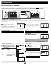
Switch Modes
After configuring, mounting and connecting your UPS System, you
are able to operate it by switching between the following operating
modes as appropriate to your situation:
AUTO/REMOTE: Switch to this mode when you
need constant, uninterrupted AC power for connected
lights, controllers or other equipment. Properly
installed and maintained, the UPS System will contin-
ue to pass-through AC power to connected equipment
and to charge your connected batteries while utility- or generator-
supplied AC power is present. Since the inverter is ON (but in
Standby) in this mode, it will automatically switch to your battery
system to supply inverter AC power to connected equipment in the
absence of a utility/generator source or in over/under voltage situa-
tions, such as in blackouts or brownouts.
OFF: Switch to this mode to shut down the UPS
System completely, preventing the inverter from draw-
ing power from the batteries, and preventing utility AC
from passing through to connected equipment or
charging the batteries. Use this switch to automatically
reset the unit if it shuts down due to overload or overheating. First
remove the excessive load or allow the unit to sufficiently cool
(applicable to your situation). Switch to “OFF”, then back to
“AUTO/REMOTE”. If unit fails to reset, remove more load or allow
unit to cool further and retry.
Optional Feature for Alternate Use of Tripp Lite Traffic
MOVE-UPS. CHARGE ONLY: The “Charge-Only” setting is
designed only for mobile applications, not for traffic signal or
security/wireless applications. When the UPS System is
switched to this position, the inverter will be disabled and bat-
tery backup power will not be supplied during a blackout,
brownout or overvoltage.
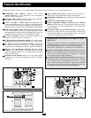
Indicator Lights
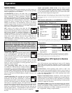
“LINE Green LED”: If the operating mode switch is
set to “AUTO/REMOTE”, this light will ILLUMI-
NATE CONTINUOUSLY when your connected equip-
ment is receiving continuous AC power supplied from
a utility/generator source.
If the operating mode switch is set to “CHARGE ONLY”, this light
will BLINK to alert you that the unit’s inverter is OFF and will NOT
supply AC power in the absence of a utility/generator source or in
over/under voltage situations.
“INV” (Inverting) Yellow LED: This light will
ILLUMINATE CONTINUOUSLY whenever connect-
ed equipment is receiving battery-supplied, inverted
AC power (in the absence of a utility/generator source
or in over/under voltage situations). This light will be
off when AC power is supplying the load. This light will BLINK to
alert you if the load is less than the Battery Charge Conserver (Load
Sense) setting.
“LOAD” Red LED: This red light will ILLUMI-
NATE CONTINUOUSLY whenever the inverter is
functioning and the power demanded by connected
equipment exceeds 100% of load capacity. (Be sure to
size your UPS model properly for the traffic signal or
other loads it is expected to support.) The light will BLINK to alert
you when the inverter shuts down due to a severe overload or over-
heating. If this happens, turn the operating mode switch “OFF”;
remove the overload and let the unit cool. You may then turn the
operating mode switch to “AUTO/REMOTE” after it has adequate-
ly cooled. This light will be off when AC power is supplying
the load.
“BATT VOLT/CHRG CURR” LEDs: If the switch is in the
“AUTO/REMOTE” position (normal setting for traffic applica-
tions), the LEDs indicate the approximate charge level and voltage
of your connected battery bank and alert you to several fault condi-
tions. See Chart for charge and voltage levels.*
* When used in alternate mobile applications, the LEDs can indicate charge rate when the
Operating Mode Switch is in the "Charge-Only" position. However, in traffic signal or
security/wireless applications, the Operating Mode Switch should never be set to the "Charge-
Only" position.
LED Function with Switch in "AUTO/REMOTE" Position
Approximate Battery Charge Level*
LEDs Battery Capacity
Illuminated (Charging/Discharging)
Green 91%–Full
Green & Yellow 81%–90%
Yellow 61%–80%
Yellow & Red 41%–60%
Red 21%–40%
All three lights off 1%–20%
Flashing red 0% (Inverter
shutdown)**
* Charge levels listed are approximate. Actual conditions vary depending on battery condition
and load. ** Inverter shutdown protects battery against damage due to excessive discharge.
Fault Condition
LEDs Fault
Illuminated Condition
All three lights Excessive discharge
flash slowly* (Inverter shutdown)
All three lights Overcharge (Charger
flash quickly** shutdown)
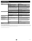
*Approximately ½ second on, ½ second off. See Troubleshooting section. Inverter shutdown
protects battery against damage due to excessive discharge.** Approximately ¼ second on, ¼
second off. Charger shutdown protects battery against damage due to overcharge. May also
indicate a battery charger fault exists. See Troubleshooting section.
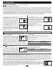
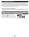
Resetting Your UPS System to Restore
AC Power
Your UPS System may cease supplying AC power or DC charging
power under certain conditions, especially in order to protect itself
from overload or to protect your electrical system. To restore normal
functioning:
Overload Reset: Switch operating mode switch to “OFF” and
remove some of the connected electrical load (ie: turn off some of
the AC devices drawing power which may have caused the overload
of the unit). Wait one minute, then switch operating mode switch
back to “AUTO/REMOTE.”
Output Circuit Breaker Reset: Alternatively, check output circuit
breaker(s) on the unit's front panel. If tripped, remove some of the elec-
trical load, then wait one minute to allow components to cool before
resetting the circuit breaker. See Troubleshooting for other possible
reasons AC output may be absent.
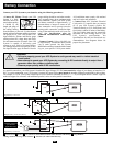
Check Battery Voltage: Your UPS is designed to keep your connect-
ed batteries constantly charged, so long as utility/generator power is
present. In the absence of utility/generator power, or as a result of
poor battery maintenance, low battery voltage may prevent AC out-
put. As applicable, recharge or replace battery.
1
2
3
4
5
6
7
1
2
1
2 3
4
5
6
7
1
2