


7T
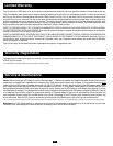
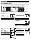
Set Battery Charging Amps—OPTIONAL (function included
on switch on 612 models)
For traffic signal UPS applications, confirm
that the setting is on low charging to length-
en the life of your batteries (especially
smaller ones), which is advisable in traffic
signal UPS applications. By setting on high
charging, your batteries will charge at maximum speed, which may
appeal for mobile applications. Check specifications for your unit’s
high- and low-charging amp options.
Battery ChargerSwitch Position
Low Charge Amps Up (factory setting)
High Charge Amps Down
CAUTION: When switching to the High Charge Amp setting, the user must ensure that the
amp hour capacity of their battery system exceeds the amperage of the High Charge Amp
setting or the batteries may be damaged or degraded.
Select Equalize Battery Charge—OPTIONAL
(Not on 612 Models)
This DIP Switch is momentarily engaged to
begin the process of equalizing the charge
state of your battery’s cells by time-limited
overcharge of all cells. This can extend the
useful life of certain types of batteries; con-
sult with your battery’s manufacturer to determine if your batteries
could benefit from this process. The charge equalization process is
automatic; once started, it can only be stopped by removing the
input power.
Setting Procedure
• Move to “Equalize” (DOWN) position for three seconds.
• Move to “Reset” (UP) position and leave it there. This is the
factory default setting.
CAUTION: Do not leave DIP switch #B3 in the down position after beginning process. Battery
charge equalization should only be performed in strict accordance with the battery manufacturer’s
instructions and specifications.
Battery Charge Switch Position
Reset Up (factory setting)
Equalize Down—momentarily
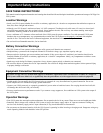
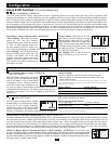
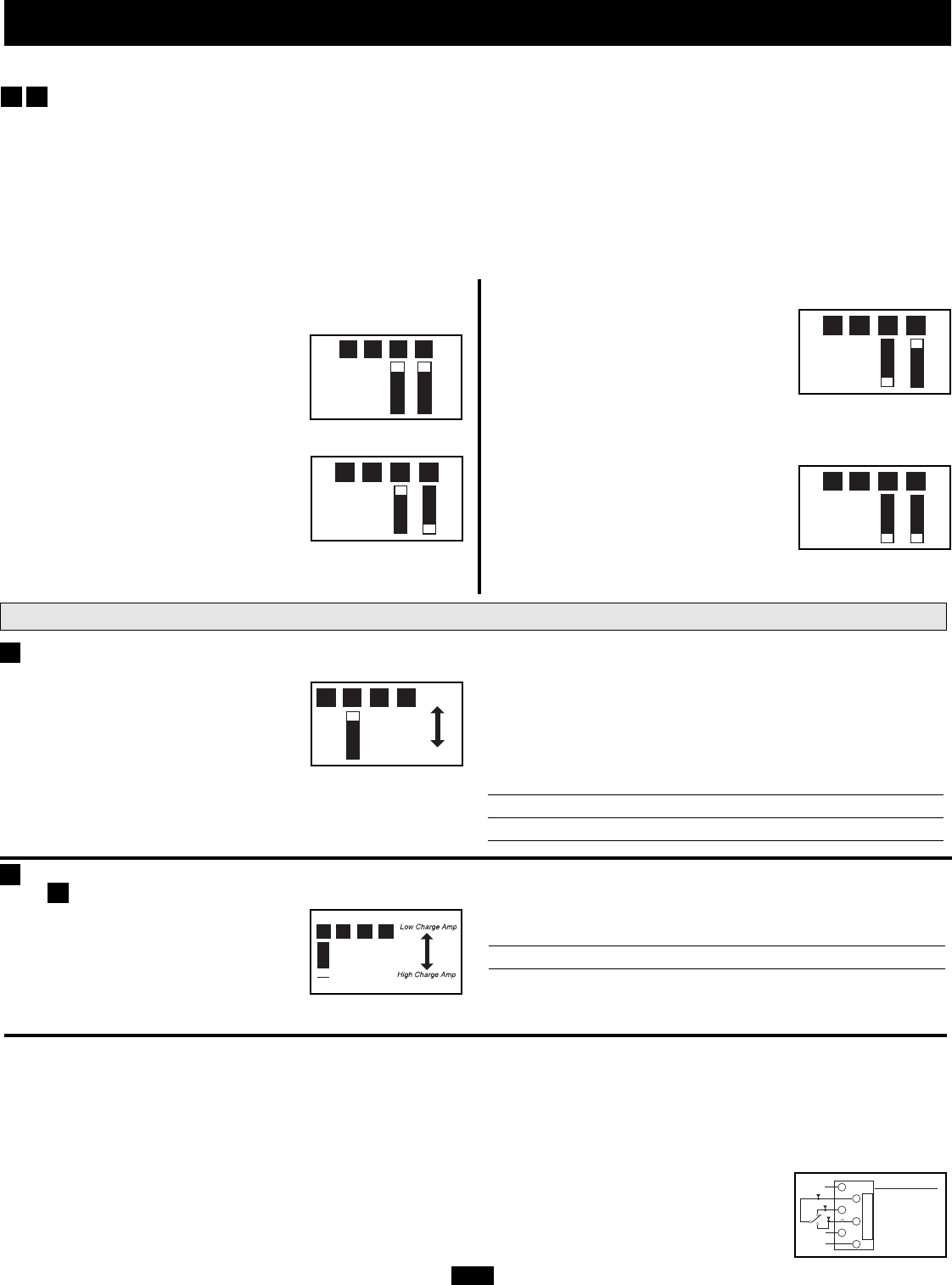
Select Battery Charger-Limiting Points—OPTIONAL
“Most Limiting” (#B2 & #B1 Up, factory
setting for 2012 and 1012 models):
Charger-limiting takes effect the moment
any 120V AC load is applied; charger out-
put falls gradually from full output at no
120V load passing through to no output at full load.
“Less Limiting” (#B2 Up & #B1 Down):
Charger-limiting begins when the UPS
System’s load reaches 33% of the UPS
System’s load rating. Charger output falls
gradually from full output at 33% of the
UPS System’s load rating to about 40% of
full output at full load.
“Least Limiting” (#B2 Down & #B1 Up,
applicable only to 2012 models): Charger-
limiting begins when the UPS System’s
load reaches 66% of the UPS System’s load
rating. Charger output falls gradually from
full output at 66% of the UPS System’s load rating to about 40% of
full output at full load. This setting IS NOT recommended for traf-
fic signal UPS applications
“No Limiting” (#B2 & #B1 Down): No
charger-limiting occurs at any load size.
Configuration
(continued)
B1B2B3B4
B1B2B3B4
B1B2B3B4
B1B2B3B4
B1B2B3B4
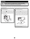
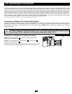
Connect Battery Temperature Sensing Cable (1012 and 2012 models only)
The battery temperature sensing function prolongs battery life by adjusting the charge float voltage level based on battery temperature. Connect
the sensor cable (the cable, included with select models, has an RJ style connector on one end and a black sensor on the other) to the RJ
style jack located on the side of the UPS System labeled “Remote Temp. Sense.” With user-supplied electrical or duct tape, affix the sensor to
the side of the battery below the electrolyte level. Make sure that nothing, not even tape, comes between the sensor and the side of the battery.
To guard against false readings due to ambient temperature, place the sensor between batteries, if possible, or away from sources of extreme
heat or cold. If the sensor cable is not used, the UPS System will charge according to its default 25º C values.
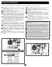
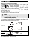
Utilize Low Battery Relay for Flashing-Red Mode or Alarm Capability—OPTIONAL (1012 and 2012 mod-
els only) All models except 612 models include an RJ type modular jack on the side panel. Attach to a user-supplied cable
and relay. Once attached, the interface will allow the UPS System to automatically relay alarms to a controller station indicat-
ing that connected battery systems are nearly depleted, to enable the controller to switch to flashing-red mode and/or send a
low battery alarm to a central control monitor.
Reset
Equaliz
e
B1B2B3B4
B4
B3
A4
1
2
3
4
5
6
Pin Configuration
2 - Common
3 - N.C.
(Normally Closed)
4 - N.O.
(Normally Open)
Note: On TMU612 and TMU1250 models, these DIP Switches are non-functional.
Group B DIP Switches (1012 and 2012 Models Only)
Select Load Sharing—OPTIONAL
Your UPS System features a battery charger that can draw a significant amount of AC power from your utility source or generator when
charging at its maximum rate. To help ensure that your unit is supplying sufficient AC power rating to its connected electrical loads, the charger’s
draw is limited by factory settings as indicated below. Tripp Lite advises against altering these settings in traffic signal UPS applications.
Failure to limit the charger's draw in combination with undersizing the UPS for connected loads could trip the AC input circuit breaker, result-
ing in interruption of pass-through utility power. To keep the sum of the unit’s AC load and charge power within the circuit breaker rating,
this charger-limiting function has four settings, allowing you to reduce the charger’s draw lower and lower, as needed, if the AC input circuit
breaker keeps tripping under the normal AC loads of devices you have connected downline from the unit. The figures show how to set your
DIP Switches to determine how heavy the connected load can be on your UPS System before charger-limiting begins.
B2B1