


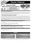


4R
Operation
(continued)
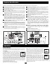
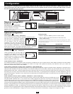
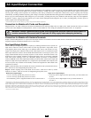
Indicator Lights
Your Inverter (as well as an optional Tripp Lite Remote Control Module) is equipped with a simple, intuitive, user-friendly set of indicator lights. These
easily-remembered “traffic light” signals will allow you, shortly after first use, to tell at a glance a wide variety of operating details.
“BATT VOLT” or “BATT VOLT/CHRG CURR” LEDs: Depending on your model, this set of three LEDs will display different operating information.
750 and 1250 models: Whether the switch is in the “AUTO/REMOTE” or “CHARGE ONLY” position, the LEDs indicate the approximate charge level
and voltage of your connected battery bank and alert you to several fault conditions. See “BATT VOLT” LED Function Chart for details.
2012 and 3012 models only: If the switch is in the “AUTO/REMOTE” position, the LEDs indicate the approximate charge level and voltage of your
connected battery bank and alert you to several fault conditions. See “BATT VOLT” LED Function Chart for details.
If the switch is in the “CHARGE ONLY” position, the LEDs indicate the approximate charge rate of the Inverter. See “CHRG CURR” LED Function Chart
for details. Note: the charge rates in the chart are expressed as percentages of the Inverter's rated charging amps. Refer to the specifications to determine
the charging amps of your specific model.
“LINE Green LED”: If the operating mode switch is set
to “AUTO/REMOTE”, this light will ILLUMINATE
CONTINUOUSLY when your vehicle is connected to
shore (or generator) power.
If the operating mode switch is set to “CHARGE ONLY”,
this light will BLINK to alert you that the unit’s inverter is OFF and will
NOT supply AC power in the absence of a utility/generator source.
“INV” (Inverting) Yellow LED: This light will
ILLUMINATE CONTINUOUSLY whenever connected
equipment is receiving battery-supplied, inverted AC
power.
“LOAD” Red LED: This red light will ILLUMINATE
CONTINUOUSLY whenever the inverter is functioning
and the power demanded by connected equipment exceeds
100% of load capacity. The light will BLINK to alert you
when the inverter shuts down due to a severe overload or
overheating. If this happens, turn the operating mode switch “OFF”;
remove the overload and let the unit cool. You may then turn the operating
mode switch to either “AUTO/REMOTE” or “CHARGE ONLY” after it
has adequately cooled.
“BATT VOLT” LED Function Chart (All models)
Approximate Battery Charge Level*
LEDs Battery Capacity
Illuminated (Charging/Discharging)
Green 91%–Full
Green & Yellow 81%–90%
Yellow 61%–80%
Yellow & Red 41%–60%
Red 21%–40%
All three lights off 1%–20%
Flashing red 0% (Inverter
shutdown)**
* Charge levels listed are approximate. Actual conditions vary
depending on battery condition and load. ** Inverter shutdown
protects battery against damage due to excessive discharge.
Fault Condition
LEDs Fault
Illuminated Condition
All three lights Excessive discharge
flash slowly* (Inverter shutdown)
All three lights Overcharge (Charger
flash quickly** shutdown)
*Approximately ½ second on, ½ second off. See Troubleshooting section. Inverter shutdown
protects battery against damage due to excessive discharge.** Approximately ¼ second on, ¼
second off. Charger shutdown protects battery against damage due to overcharge. May also
indicate a battery charger fault exists. See Troubleshooting section.
“CHRG CURR” LED Function Chart (2012 and 3012 models only)
Approximate Charge Rate Indication
LEDs
Illuminated Charge Rate
All three lights on Overcharge
error*
Red 75% - 100%
Red & Yellow 50% - 75%
Yellow 25% - 50%
Green 0% - 25%
All three lights off 0%
* If all three lights remain on, an internal fault may exist. Turn off and disconnect the unit.
Then, call Tripp Lite at (773) 869-1234 for assistance.
1
2
3
4
5
6
7
1
2 3
4
5
6
7
1
2
1
2
1
2 3
4
5
6
1
2
3
4
5
6
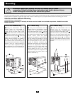
Resetting Your Inverter to Restore AC Power
Your Inverter may cease supplying AC power or DC charging power in
order to protect itself from overload or to protect your electrical
system. To restore normal functioning:
Overload Reset: Switch operating mode switch to “OFF” and remove
some of the connected electrical load (ie: turn off some of the AC
devices drawing power which may have caused the overload of the
unit). Wait one minute, then switch operating mode switch back to
either “AUTO/REMOTE” or “CHARGE ONLY.”
Output Circuit Breaker Reset: Alternatively, check output circuit
breaker(s) on the unit's front panel. If tripped, remove some of the
electrical load, then wait one minute to allow components to cool
before resetting the circuit breaker. See Troubleshooting for other
possible reasons AC output may be absent.