


5R
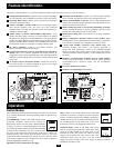
Connect Remote Control—OPTIONAL
An 8-conductor telephone style receptacle on the front panel is included for use with an optional remote control module (included). The remote module
allows the Inverter to be mounted in a compartment or cabinet out of sight, while operated conveniently from within the cab of your vehicle. See
instructions packed with the remote control module.
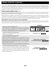
Connect Battery Temperature Sensing Cable—OPTIONAL—(Select models only)
The battery temperature sensing function prolongs battery life by adjusting the charge float voltage level based on battery temperature. Connect the sensor
cable (the cable, included, has an RJ style connector on one end and a black sensor on the other) to the RJ style jack located on the side of the Inverter
labeled “Remote Temp. Sense.” With user-supplied electrical or duct tape, affix the sensor to the side of the battery below the electrolyte level. Make sure
that nothing, not even tape, comes between the sensor and the side of the battery. To guard against false readings due to ambient temperature, place the
sensor between batteries, if possible, or away from sources of extreme heat or cold. If the sensor cable is not used, the Inverter will charge according to its
default 25º C values.
Utilize Automatic Generator Starter Capability—OPTIONAL—(Select models only)
Although not typically applicable to utility/work truck situations, select Inverter models offer an RJ type modular jack on the
side panel labeled “Generator Start.” If your current fleet is already equipped with generators, select Tripp Lite Utility/Work
Truck Inverters provide your crews the option of quiet power for residential environments or late-night job sites. When wattage
loads are within the Inverter's ratings, crews can avoid the power overkill, fuel consumption, fumes and noise of generator use.
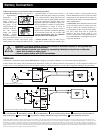
To tie the Inverter and generator together, simply connect the generator's AC power output to the Inverter's AC input. The Inverter will automatically charge
the battery when generator power is available, and generator power will automatically pass-through for use via the Inverter's GFCI receptacles or hardwire
terminals (depending on model). To automatically activate the generator when battery voltage runs low, attach to vehicle generator ON/OFF switching
mechanism with user-supplied cable (see Pin Configuration Diagram). Once attached, the interface will allow the Inverter to automatically switch a vehicle
generator on when connected battery voltage levels are low (11.6 VDC) and switch it off when battery voltage levels are high (14.1 VDC).
Configuration
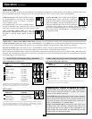
DIP SWITCH
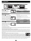
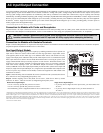
Select Battery Type—REQUIRED
Using a small tool, set the DIP switch to match
the type of batteries you connect.
Battery Type Switch Position
Gel Cell (Sealed) Battery Up
Wet Cell (Vented) Battery Down (factory setting)
Note: Tripp Lite recommends that users only change settings for the DIP switches and controls described below. Additional DIP switches and
controls located in the unit's DIP switch panel or in other areas are preset to optimize the unit's operation. Setting these DIP switches or controls
may adversely affect the unit's operation.
A1A2A3A4
Required Configuration
1
DIP SWITCH
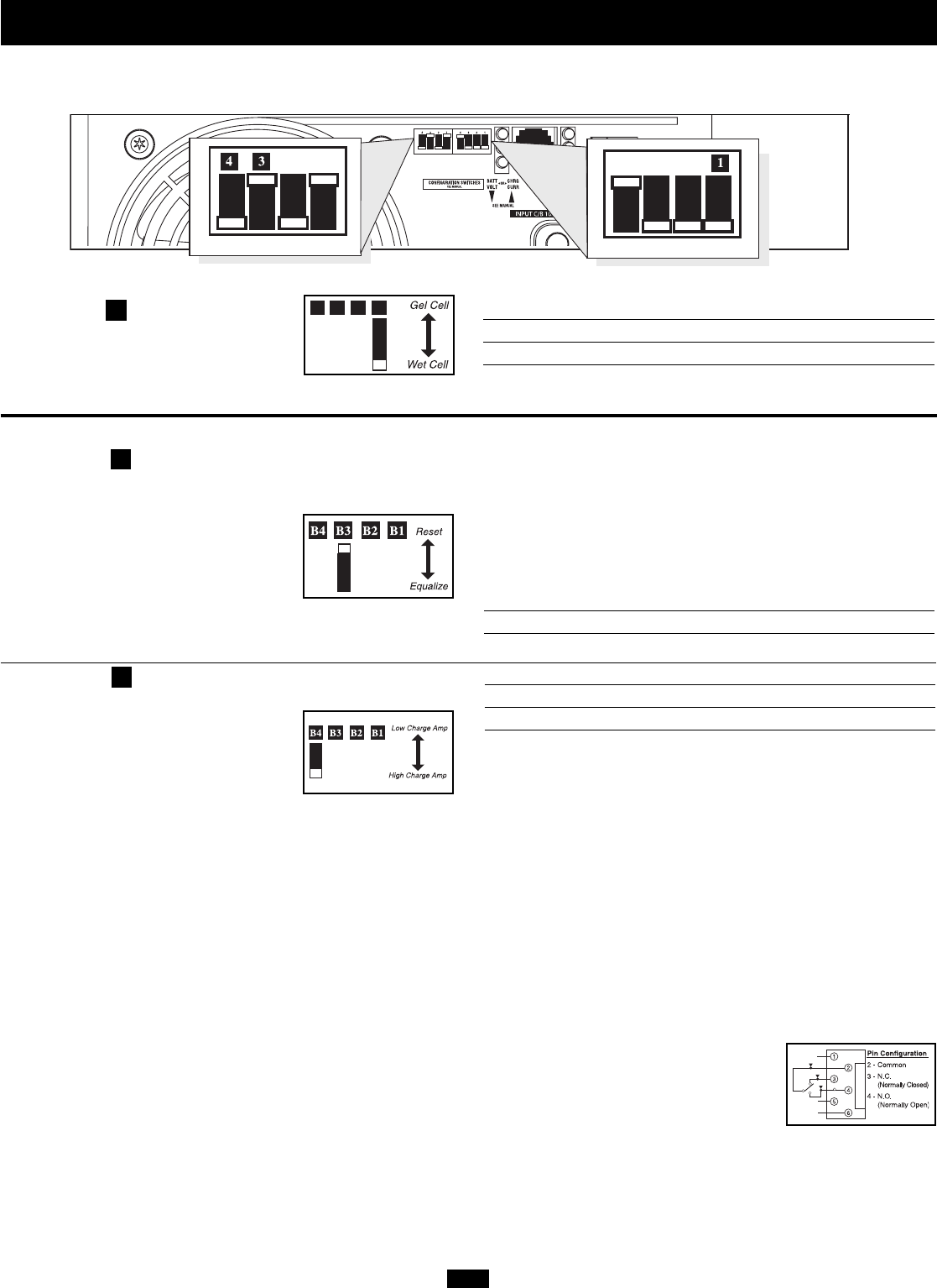
Set Battery Charging Amps—OPTIONAL
Check specifications for your unit’s high- and
low-charging amp options. By setting on high
charging, your batteries will charge at
maximum speed. By setting on low charging
(factory setting), you lengthen the life of your
batteries (especially smaller ones).
Battery Charger Switch Position
Low Charge Amps Up
High Charge Amps Down (factory setting)
DIP SWITCH
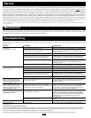
Select Equalize Battery Charge—OPTIONAL
(For use when using auxiliary batteries. See Battery Selection section.)
This DIP Switch is momentarily engaged to
begin the process of equalizing the charge state
of your battery’s cells by time-limited
overcharge of all cells. This can extend the
useful life of certain types of batteries; consult
with your battery’s manufacturer to determine if your batteries could
benefit from this process. The charge equalization process is automatic;
once started, it can only be stopped by removing the input power.
Setting Procedure
• Move to “Equalize” (DOWN) position for three seconds.
• Move to “Reset” (UP) position and leave it there. This is the
factory default setting.
CAUTION: Do not leave DIP switch #B3 in the down position after beginning process. Battery
charge equalization should only be performed in strict accordance with the battery manufacturer’s
instructions and specifications.
Battery Charge Switch Position
Reset Up (factory setting)
Equalize Down—momentarily
4
3
Optional Configuration
CAUTION: The Battery Type DIP Switch setting must match the type of batteries you connect, or your batteries may be degraded or damaged over an extended period of time. See “Battery
Selection,” for more information.