


32
1
5
9
3
7
11
2
6
10
4
8
12
13
14
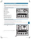
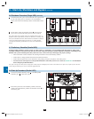
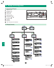
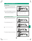
10 – Display and Confi guration
10-1 Control Panel Diagram
“NORMAL” LED•
“BATTERY” LED•
“BYPASS” LED•
“FAULT” LED•
LCD Status Screen•
“ESC” (Escape) Button•
Scroll Buttons (• and )
Enter Button (• )
ON Button•
OFF Button•
“EPO” (Emergency Power Off) Button•
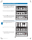
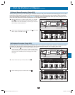
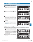
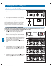
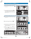
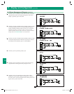
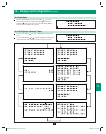
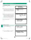
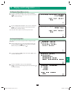
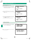
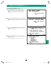
10-2 Display Hierarchy
A
B
C
D
E
F
G
H
I
J
K
Control Panel
E
F
G
K
A
B
C
D
H
I
J
200706017 93-2688 SU manual 4C.indd 32200706017 93-2688 SU manual 4C.indd 32 11/29/2007 2:02:51 PM11/29/2007 2:02:51 PM