


16 Port Ethernet Switch With Optional Fiber Port
Tyco Electronics Page 5
Completing The Installation
When the switch has been installed as specified above, then the
unit can be configured as detailed below:-
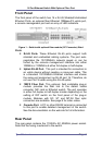
1. Apply AC power to the switch. The green Power LED on the
front panel should light.
2. Connect the Cat. 5/5e twisted pair cables from the network
partner devices to the RJ-45 ports on the front panel of the
switch. In certain cases a cross-over RJ-45 cable may be
needed. When a connection is obtained, the green LK/ACT LED
associated with the port will light.
3. If the fiber uplink is not used, then connect the RJ-45 uplink port
to the required device (router, server, etc). When a connection
is obtained, the green LK/ACT LED associated with port 16 will
light. Ensure that there is no connection to the standard RJ-45
port 16.
4. If the fiber uplink is used, then connect the fiber link to the
partner device (media converter, fiber NIC card or fiber switch
etc). Ensure that the fiber uplink is set in the correct duplex
mode (default = Full Duplex) using the front panel switch on the
module. Verify that the green Link LED on the fiber module is lit
which indicates that the optical link is valid.
5. If advanced modes such as port trunking or port-based VLANs
are needed, then use the console port to configure the switch.
See the console port instructions on the web site for further
details.
6. If there are legacy devices that do not support auto-negotiation
connected to the RJ-45 ports, then it may be necessary to
program the switch using the console port. See the console port
instructions on the web site for further details.
7. Note that auto-negotiation can take up to 30 seconds to
complete depending on the partner device.