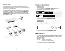
Hardware Description
The Front Panel
The Front Panels of the Dyna-Switch/16 and 24 consist of
10/100Base-TX RJ-45 ports and LED Indicators.
Figure 2. Front Panel views of Dyna-Switch/16 and 24
The Rear Panel
The 3-pronged power plug is located at the rear panel of the
switches as shown in the Figure 3. The Switch operates on AC in the
range 100-240V AC, 50-60Hz.
Figure 3. Rear panel view of the Dyna-Switch/16 and 24
LED Indicators
The LED Indicators give real-time information of systematic operation
status. The following table provides descriptions of the LED status
and their meanings.
Per Device: Power
Per Port: LINK/ACT ( Link/Activity )
FDX/COL ( Full duplex/Collision )
For LED indication details, please refer to page 4.
36
LK/ACT
FD/COL
FD/COL
LK/ACT
Dyna-Switch/16
16 Port 10
/
100Base-TX Switch
POWER
POWER
LK/ACT
FD/COL
FD/COL
LK/ACT
Dyna-Switch/24
24 Port
10
/
100Base-TX Switch
Segment Bridge
For enterprise networks where large data broadcasts are constantly
processed, these switches are an ideal solution for department users to
connect to the corporate backbone.
In the illustration below, two Ethernet switches, with PCs, print servers,
and a local server attached, are both connected to a Dyna-Switch. All of
the devices in this network can communicate with each other through
the Dyna-Switch. Connecting servers to the switch allows other users to
access the server’s data.
Printers
Server
Workstations
L
K
/
A
C
T
F
D
/COL
F
D
/CO
L
L
K
/
A
C
T
D
yn
a
-S
witc
h
/1
6
1
6
Po
r
t
1
0
/
1
0
0
B
a
s
e-T
X
S
w
itc
h
P
O
W
E
R
Figure 6. Segment Bridge Application


