


Configuring Channel Racks
4–6 7017 6300–005
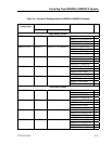
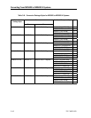
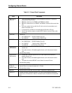
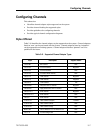
Table 4–5. Configuring Power Net in Channel Racks
Area Recommendation
Configuration For NX5820 systems, if the channel racks are daisy chained to one another and the CEC
section, use 9 Pin D to 9 Pin D Power Net cables (Style CBL8820-xxx, cable assembly 3446
6110-xxx).
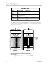
The 9 Pin “Power Net In” connector (J5) is located on the left side in the rear of the channel
rack. The 9 Pin “Power Net Out” connector (J4) is next to it.
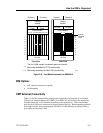
Power Net
Address
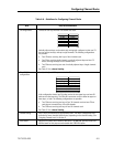
Switches 3 (MSB) through 8 (LSB) are used for the Power Net address assigned to the
channel rack. Switch 1 and 2 are not applicable.
Termination Channel racks have internal termination. Only install Power Net terminator activation
jumpers at JP2 and JP4 if this channel rack is the last on the Power Net chain.
Reference Refer to Channel Rack Installation Guide (3953 3893–502) or higher for further
information on channel racks.