


Table of Contents
1 INTRODUCTION . . . . . . . . . . . . . . . . . . . . . . . . . 1
The Model 1005 Repeater Hub . . . . . . . . . . . . . . . . . . . . . . .1
Model 1005 Repeater Hub Features . . . . . . . . . . . . . . . . . . . . .1
Networking the Model 1005 Repeater Hub . . . . . . . . . . . . . . . .2
Model 1005 Repeater Hub Connectors, Indicators,
and Switch . . . . . . . . . . . . . . . . . . . . . . . . . . . . . . . . . . .3
2 SITE CONSIDERATIONS. . . . . . . . . . . . . . . . . . . . 4
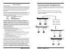
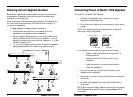
Ensuring Correct Segment Number . . . . . . . . . . . . . . . . . . . .5
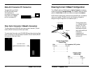
Ensuring Correct 10BaseT Configuration . . . . . . . . . . . . . . . .8
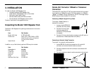
3 INSTALLATION. . . . . . . . . . . . . . . . . . . . . . . . . . . 7
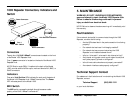
Unpacking the Model 1005 Repeater Hub . . . . . . . . . . . . . .7
Installing Slide-In Cards . . . . . . . . . . . . . . . . . . . . . . . . . . . . .8
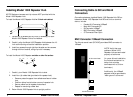
Installing Model 1005 Repeater Hub . . . . . . . . . . . . . . . . . . .9
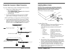
Connecting Cable to SIC and RJ-45 Connectors . . . . . . . . . .10
BNC Connector/10Base2 Connection . . . . . . . . . . . . . . . . . . .10
Twisted Pair Connector/10BaseT Connection . . . . . . . . . . . . .11
Female AUConnector/10Base5 or Transceiver Connection . . .12
Male AUIConnector/PC Connection . . . . . . . . . . . . . . . . . . . .13
Fiber OpticConnector/10BaseFL Connection . . . . . . . . . . . . . .13
Connecting Power to Model 1005 Repeater . . . . . . . . . . . .14
4 OPERATION . . . . . . . . . . . . . . . . . . . . . . . . . . . . 15
Monitoring Power LED . . . . . . . . . . . . . . . . . . . . . . . . . . . .15
Monitoring Status LEDs . . . . . . . . . . . . . . . . . . . . . . . . . . . .15
5 MAINTENANCE . . . . . . . . . . . . . . . . . . . . . . . . . 16
Fault Isolation . . . . . . . . . . . . . . . . . . . . . . . . . . . . . . . . . . .16
Technical Support Contact . . . . . . . . . . . . . . . . . . . . . . . . .16
POLICY AND PROCEDURE . . . . . . . . . . . . . . . . . . . . . . . . . 17
CABLE SPECIFICATIONS. . . . . . . . . . . . . . . . . . . . . . . . . . . . 19
Model 1005 Repeater Hub SPECIFICATIONS. . . . . . . . . . . 21
Model 1005 24-Port
i
19
Ethernet™ Repeater Hub
ETHERNET CABLE SPECIFICATIONS
AUI Cable and Connector Specifications
The cable is a special 4-pair individually shielded with an overall braided
shield.
Maximum AUI Cable Length: 50 meters (165 feet)
AUI Connector Characteristics:
AUI Port: Male DB-15 with locking posts.
AUI Connection: Cable shell must be grounded.
Connector Legend: 1 Logic Ref. 6 Power Return 11 Logic Ref
2 Collision+ 7 N/C 12 Receive
3 Transmit+ 8 Logic Ref. 13 Power
4 Logic Ref. 9 Collision-- 14 Logic Ref.
5 Receive+ 10 Transmit- 15 N/C
10BaseFL Cable and Connector Specifications
The physical characteristics of the 10BaseFL cable must meet or exceed IEEE
802.3 10BaseFL specifications.
10BaseFL Cable Characteristics:
Fiber Optic Cable Recommended: 62.5/125 µm multimode fiber
Optional: 100/140 µm multimode fiber
85/125 µm multimode fiber
50/125 µm multimode fiber
Fiber Optic Transmitter Power: Average power: -15.0 dBm
Peak power:-12.0 dBm ±1dBm
Fiber Optic Receiver Sensitivity: Average sensitivity: -27.4 dBm
Bit error rate: ≤10
-10
Maximum Cable Length: 2000 meters (6500 feet)
10BaseFL Connector Characteristics:
ST type connectors (SMA type available upon request)
10Base5 Cable and Connector Specifications
The physical characteristics of the 10Base5 cable must meet or exceed IEEE 802.3
10Base5 specifications.
10Base5 Cable Characteristics:
Cable type: RG8 Solid Coaxial (ThickNet)
Impedance: 50 Ω @ 10 MHz
Capacitance: 26pF/ft
Maximum Cable Length: 500 meters (1650 feet)
Maximum number network connections: 100
Minimum distance between connections: 2.5 meters (8.2 feet)
Terminate 10Base5 cable at one end using a 50 ohm terminator and at the
other end using a 50 ohm terminator grounded to earth ground.
Maximum number of terminal devices on Ethernet network: 1024