


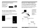
Model 1005 24-Port
16
3
Ethernet™ Repeater Hub
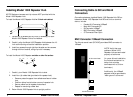
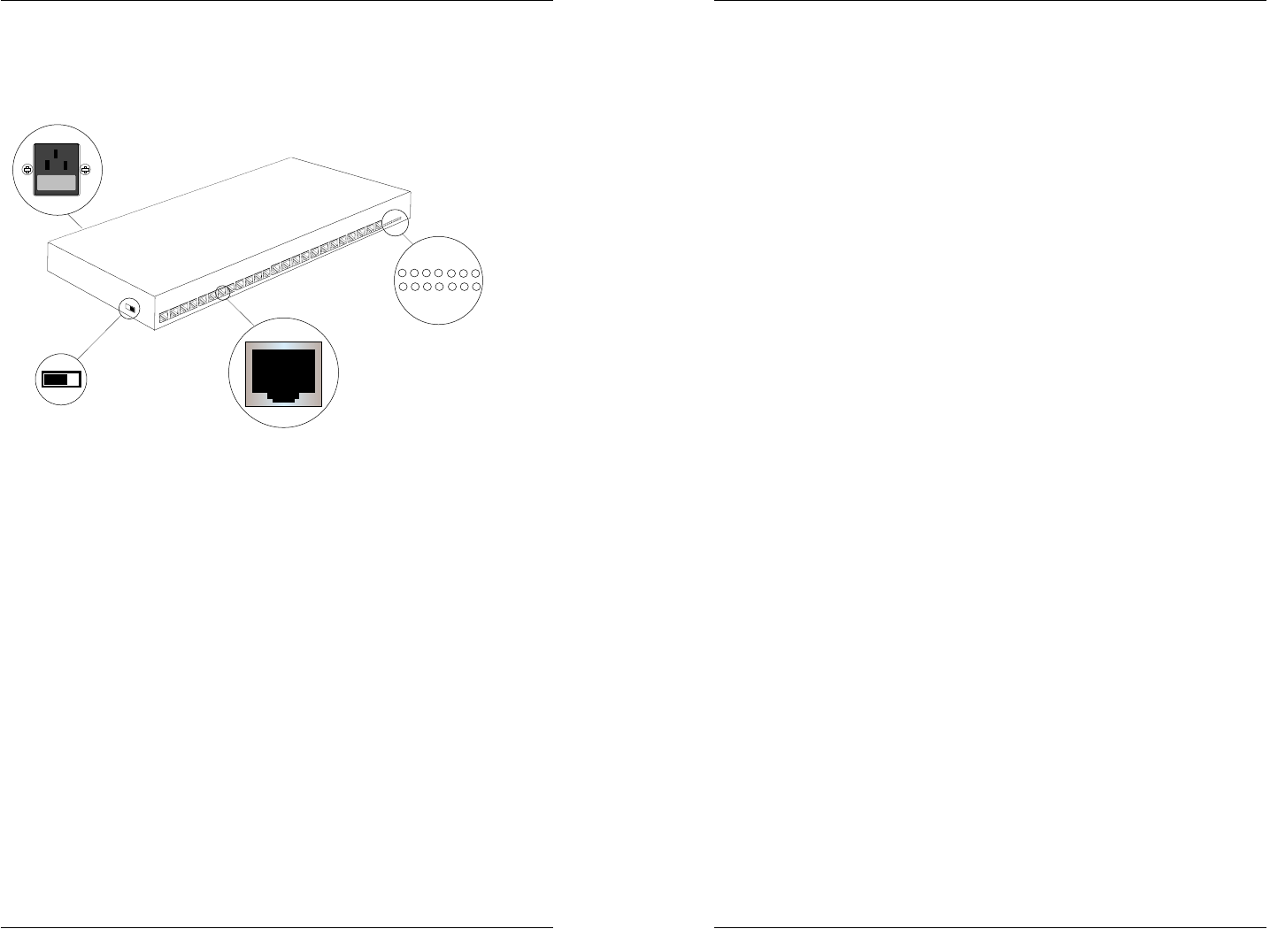
1005 Repeater Connectors, Indicators and
Switch
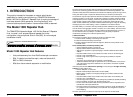
Connectors
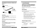
Twenty-four (24) RJ-45 10BaseT connectors are located on the front
of the Model 1005 Repeater Hub.
One (1) power connector is located on the back of the Model 1005
Repeater Hub.
NOTE: Slide-In cards (SICs), if installed at the back of the Model
1005, provide additional fiber optic, male and female AUI, BNC, or
RJ-45 connectors.
Indicators
One set of Link/Partition LEDs indicate (for each port) the status of
the Model 1005 Repeater Hub 10BaseT connections. The Power
LED indicates power to the Model 1005.
MDI Switch
The MDI switch reverses the straight-through/crossover cable
polarity of the RJ-45 10BaseT connector #1.
5. MAINTENANCE
WARNING: DO NOT, UNDER ANY CIRCUMSTANCES,
open and attempt to repair the Model 1005 Repeater Hub.
Failure to observe this warning could result in personal
injury or death from electrical shock.
NOTE: Failure to observe the above warning will immediately void
the warranty.
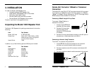
Fault Isolation
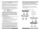
If two network devices fail to communicate through the 1005
Repeater, consider the following:
• Are the LEDs described in the previous section functioning
properly?
• Do network devices have Link Integrity enabled?
• Do network devices communicate when the 1005
Repeater is not installed between them?
• Is flat or “silver satin” wire used in site internal wiring?
• Are internal wiring patch cords, punch down blocks, and
wall jacks properly pinned or configured?
• Is the thinnet cable unbroken and properly connected?
• Are network interface cards properly configured?
Technical Support Contact
For assistance in fault isolation and in maintaining the Model 1005
Repeater, contact:
Technical Support (800) 260-1312
or your local distributor.
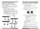
Link/Partition Indicators
Port 1
MDI Switch
RJ-45 Connectors
110-120
220-240
Power Connector