4
microfilter on the cable that connects your ADSL router to the telephone jack unless your
microfilter has a connection for both the router and the phone.
Step 2. Connect the Cables
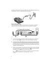
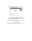
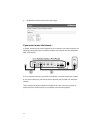
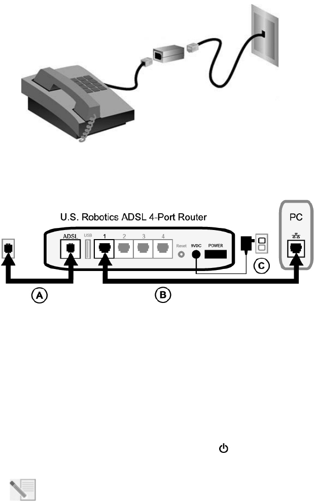
Use the supplied Ethernet cable to connect the router to the computer. This diagram
shows you how the devices will be connected when the installation is complete:
To make the needed connections, follow these steps:
A. Connect one end of the grey telephone cable to the telephone port on the back of
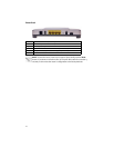
your router (labeled ADSL). Connect the other end to the telephone wall jack.
B. Connect the Ethernet cable. Although you can connect up to four systems this way,
you should start with one and connect additional devices only after the initial setup
is complete. Insert one end of the Ethernet cable into one of the ports on the back of
the router (labeled 1, 2, 3, and 4). Connect the other end to the Ethernet port on your
computer’s network interface card.
C. Plug the AC power adapter into the 9VDC jack on the back of your router. Then plug
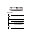
the AC power adapter into a standard wall outlet. If the LED on the front panel is
not lighted, press the Power switch on the back of the router.
NOTEThis product is intended to be supplied by a UL Listed Direct Plug-in
Power Unit marked Class 2 and rated 9V DC, 1200 mA.


