


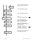


Version 1.0 March 1, 2000 Page 21
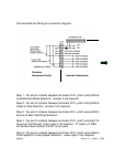
Speed value is determined by P402. A selection of P402=100% will be
a full speed reference setpoint.
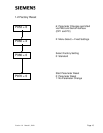
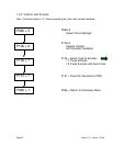
Step 6: Fault Status is provided by a 24 Vdc signal at terminals X101
pin#3 with respect to pin#2. Leave open if not required.
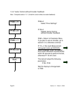
Step 7: Drive Operating Status is provided by a 24 Vdc signal at
terminals X101 pin#4 with respect to pin#2.
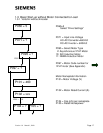
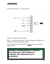
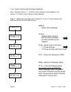
Step 8: Connect external speed reference 0-10Volt or 4-20 mA (CUVC
board mounted jumper S3 pin 2 and 2 must be closed for mA input).
Adjust over the full range and monitor P447. With a zero input r447
should read near 0.00, and with full value r447 should read near 100%.
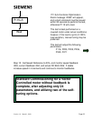
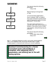
Step 9: Connect the motor to the load, unless the plan is to install an
encoder feedback or change to Vector Control.
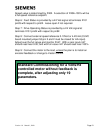
Standard Commissioning for a Volts/Hz
controlled motor without feedback is
complete, after adjusting only 19
parameters.