


9
2 Casing, System Boards and Video
System Board, Switches and Jumpers
System Board, Switches and Jumpers
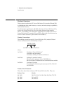
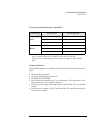
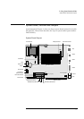
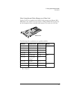
As mentioned in Chapter 1, there are three system board options for models
520 and 525. This section describes the Type A system board (part number
D4051-63001).
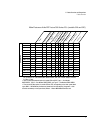
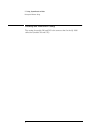
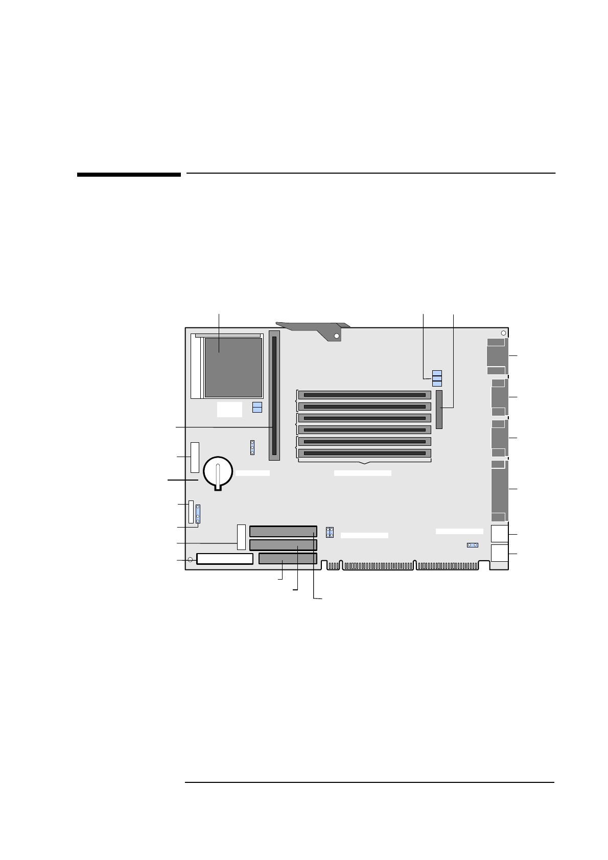
System Board Layout
1
13
1
1
2
C2
C1
B2
B1
A2
A1
24
2
2
3
3
J7
BANK A BANK B BANK C
J1
J6
JP4
SW1
SW2
Floppy Disk Drive Connector
CD-ROM Connector (IDE Channel 2)
HDD Connector (IDE Channel 1)
Video
Serial B
Serial A
Parallel
Keyboard
Mouse
Main Memory Sockets
Cache Memory
Processor Socket
Power Connector
Status Panel VE
Power
Connector 3.3 V
External Battery
Connector (not used)
Backplane Connector
VESA Feature Connector
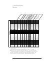
Multi-purpose Switch
CPU Core
Frequency
CPU Bus Frequency
Cache Jumper
Power-on Spacebar
External Start Connector
Battery