


Manual
9/11/2014
PSFEM1xxxGQxxx
Viking Technology
Revision B
Page 19 of 33
www.vikingtechnology.com
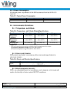
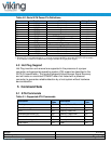
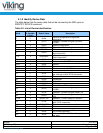
Table 4-2: Serial ATA Power Pin Definitions
Pin
Function
Definition
Mating Order
P1
3.3V_1
No connection
2nd
P2
3.3V_2
No connection
2nd
P3
3.3V_3
No connection
1st
P4
GND_1
Ground
1st
P5
GND_2
Ground
1st
P6
GND_3
Ground
1st
P7
5V_1
5VDC Power (pre-charge)
1st
P8
5V_2
5VDC Power
2nd
P9
5V_3
5VDC Power
2nd
P10
GND_4
Ground
1st
P11
Activity
Device Activity Signal (See note1)
2nd
P12
GND_5
Ground
1st
P13
12V_1
No connection
1st
P14
12V_2
No connection
2nd
P15
12V_3
No connection
2nd
Notes:
1) Remote LED is not implemented, pin 11 may be connected to GND to allow the ACTIVITY LED to remain
on to indicate a Power On condition when using a standard ATX type power supply.
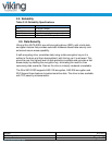
4.3 Hot Plug Support
Hot Plug insertion and removal are supported in the presence of a proper
connector and appropriate operating system (OS) support as described in the
SATA 2.6 specification. This product supports Asynchronous Signal Recovery
and will issue an unsolicited COMINIT when first mated with a powered
connector to guarantee reliable detection by a host system without hardware
device detection.
5 Command Sets
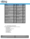
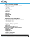
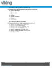
5.1 ATA Commands
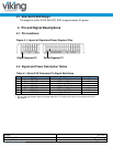
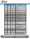
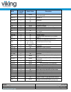
Table 5-1: Supported ATA Commands
Description
Op
Code
Description
Op
Code
Check power mode E5h Security Disable Password F6h
Data Set management 06h Security Erase Prepare F3h
DCO B1h Security Erase Unit F4h
Download Microcode PIO 92h Security Freeze Lock F5h
Download Microcode DMA 93h Security Set Password F1h
Execute drive diagnostic 90h Security Unlock F2h
Flush cache E7h Seek 70h