VXI Technology, Inc.
22 CT-100C Installation
REMOTE POWER-ON OPTION
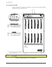
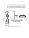
If the CT-100C mainframe is to be installed in a remote location, it is possible to apply and
remove power from the unit via the remote power pins located on connector J201. To utilize the
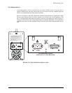
remote power feature, set the front panel switch to the standby position. Remove the power cord,
then remove the power supply from the chassis and place the jumper on the power interface board
to the 2 – 3 position (see
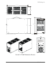
Figure 2-1 for power supply removal instructions). The power interface
board will be located inside the mainframe at the top right. Doing this will disable the front panel
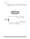
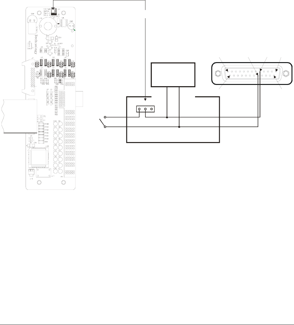
power switch. Pins 5 and 18 can now be used to remotely control the powering of the chassis. The
circuit is diagramed below:
Power Interface Board
Pin 13 Pin 1
Pin 5Pin 18
Pin 25
Power Interface Board
Front
Panel
Switch
12
3
Pin 18
Pin 5
Pin 14
Power
Supply
Jumper Location
FIGURE 1-1: REMOTE POWER-ON SWITCH WIRING


