


USER’S MANUAL — Please read before using this equipment.
© 2007 Wagan Corporation.
All Rights Reserved.
Wagan and Wagan.com are trademarks used by Wagan Corporation.
13
8000W Power Inverter
By Wagan Tech
www.wagan.com
14
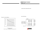
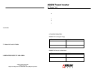
5.4 Fusing requirements
Total AC Watts Negative cables (-) Positive Cables(+)
2500 or lower One One
2500 or more but
less than 5000
Two Two
5000 to 8000 Four Four
NOTE: It is important that for this 8000 watt inverter has main battery fuses
connected to the positive (+) battery cable(s) as close as possible to the connected
battery bank’s positive terminal. The fuse amperage rating must be sized to allow
simultaneous operation of all the AC appliances to be powered, allowing for the
momentary high start-up current r equ irements of inductive loads. Use the
recommended fuse block (fuse holder) and fuse, or an electrical equivalent. ANL
type fuses and fuse holders are readily available from marine supply dealers. The
fuse and fuse holders may be connected in parallel to provide the required
protection. There are larger capacity fuses and fuse holders available. Make sure
that if the inverter is operatin g at 8000 watts that the battery is fused at greater
than 800 amps.
6. CONNECTING THE INVERTER
6.1 General information
Loose connections will result in a severe voltage drop that can cause damage to
the conductors and insulation and cause sparking.
Reverse polarity connection will blow the fuses in the inverter and can cause
permanent damage to the inverter.
The fuses are very important to protect equipment, batteries and personnel. The
fuses protect against battery explosion if the cables that connect to the inverter
accidentally short. READ AND COMPLY WITH THE WARNING BELO W.
Damage caused by reverse polarity will void the warranty.
6.2 Procedure
WARNING
1 Make sure the cables are the proper gage and have the fuse holders as close to
the battery bank’s Pos (+) terminal.
EXPLODING BATTERIES CAN SPRAY MOLTEN LEAD, HOT
SULFURIC ACID AND OTHER METAL AND PLASTIC FRAGMENTS.
BATTERIES THAT ARE CHARGING OR UNDER HIGH DISCHARGE
RATES PRODUCE EXPLOSIVE HYDROGEN GAS INTO THE
SURROUNDING AREA. BE SAFE - FUSE THE BATTERY BANK AND
MAKE SURE THE BATTERIES ARE PROPERLY VENTILATED.
2. Install the fuses in the Pos (+) cable.
3. Make sure the ON/OFF switch located on the front panel of the inverter is in
the OFF (0) position. Disconnect any remote switch from the connector on the
front panel.
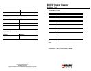
DC Cable Gage
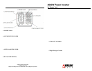
4. Locate the Ground Lug Terminal at the rear of the inverter. Connect an
insulated 6 gage copper wire to the terminal. The other end of the ground wire is
connected to a “proper” grounding point. Use the shortest practical length of wire.
Connect this wire to the chassis of your vehicle or to the grounding system in
your boat. In a city, the ground wire can connect to a metal cold water pipe that
goes underground. In remote locations, the ground wire can be connected to an
“earth ground”. This can be an attachment to a six foot long copper clad metal rod
driven into the ground. In the unlikely event of a short circuit, operating the
inverter without proper grounding can result in electrical shock. At the factory,
the negative DC terminals are also electrically connected to the ground terminal.
Minimize cable losses by using the thickest wire available, and the shortest
practical length. If the inverter and the battery are positioned within four feet of
each other, a minimum of 0 gage (zero gage) insulated copper wire should be
used to make the connections. If the distance is longer than 4 feet, heavier wire
will be required.
Because multiple battery cables are used with this inverter, keep cable gages and
lengths the same. This will ensure that cable losses will be evenly distributed. Use
the following table as a guide to the number of cable connections required. Be
sure to include any surge wattage in determining the cable configurations.
Remember that terminals also have current carrying
limits.