Preliminary
2 Input/Output and Power Connections
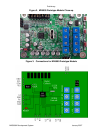
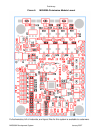
Connect Inputs, Outputs, Power and Ground as described below. Please see Figures 2 and
3 for additional illustrations.
Connect Inputs
• Three sets of stereo inputs are provided. Located on the bottom edge of the PCB,
these are labeled as LI1/RI1, LI2/RI2, and LI3/RI3. Each stereo pair uses a common
ground, labeled “G”, located between the left/right inputs.
• Connect stereo inputs and ground(s) as needed.
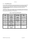
• All analog inputs support 4Vpp maximum input levels.
Connect Outputs
• Connect stereo outputs, labeled LO and RO, on the left side of the PCB. LO and RO
use a common ground labeled GND between the LO and RO connection points.
• Connect subwoofer output (labeled SUB) and ground (labeled GND) if needed.
• All analog output support 4Vpp maximum input levels.
Connect Power Supply and Ground
• Provide an external 5.0V DC and ground to the 5VIN and GND pins to the upper right
corner of the PCB. This needs to be a well regulated analog supply, since this voltage
is connected directly to the analog_Vcc of the device without additional regulation.
MX5000A Development System January 2007


