Preliminary
3.3 Digital Audio Input/Ouput
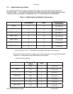
For digital audio I/O, the system supports three stereo inputs and two stereo outputs as
shown in Table 1. All inputs and outputs are synchronous with shared clock and synch pins.
The digital audio input/output is supported only in I
2
C Slave Mode of the MX5000A.
Table 1. Digital Audio Input/Output Connections
PIN NUMBER GPIO
CONNECTION ON
THE BOARD
Clock
1 0 Pin 2 of J13
Synch
2 1 Pin 2 of J12
Digital Input0
3 2 Pin 2 of J11
Digital Input1
4 3 Pin 2 of J10
Digital Input2
5 4 Pin 2 of J8
Digital Output0
8 5 Pin 2 of J9
Digital Output1
9 6 Pin 2 of J6
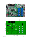
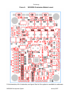
* pin 2 of Ji (were i=6, 5,...13) located on the edge of the board. See Figure 6.
Please note: There are pull-up resistors connected to those pins. You may decide to leave
them as is or to disconnect them, depending on your system.
The list of those resistors:
Pull-up to VIO
resistor
GPIO
Clock
R10 0 Pin 2 of J13
Synch
R11 1 Pin 2 of J12
Digital Input0
R12 2 Pin 2 of J11
Digital Input1
R13 3 Pin 2 of J10
Digital Input2
R14 4 Pin 2 of J8
Digital Output0
R15 5 Pin 2 of J9
Digital Output1
R16 6 Pin 2 of J6
MX5000A Development System January 2007


