


7-6
Alarm Configuration
3. After defining the "Unit to Configure" parameter, use items 2, 3, and 4 to select
Load Shedding parameters for the selected branch or line. The Branch/Line Load
Shedding Configuration Menus offer the following parameters:
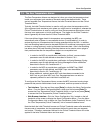
1. Enable: Enables/Disables Load Shedding for the corresponding alarm. When
enabled, the MPC will switch the user specified plugs whenever current load
exceeds the Alarm Set Threshold value. (Default = Disable.)
2. Plug State: Determines whether the selected plugs/plug groups will be
switched On or Off when Load Shedding is enabled and current load exceeds
the user-defined Alarm Set Threshold. For example, if the Plug State is set to
"Off", then the selected plugs/plug groups will be switched Off when the Alarm
Set Threshold is exceeded. (Default = Off.)
3. Auto Recovery: Enables/Disables the Auto Recovery feature for the selected
unit/branch/line. When both Load Shedding and Auto Recovery are enabled,
the MPC will return plugs to their former On/Off state after the current load falls
below the Alarm Clear Threshold value. This allows the MPC to "undo" the
effects of the Load Shedding feature after the current load has returned to an
acceptable level. (Default = Off.)
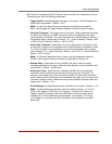
4. Plug Access: Determines which Plug(s) will be switched when the current
load exceeds the Alarm Set Threshold and the Load Shedding feature is
triggered. For example, if plugs A1, A2 and A3 are selected, then these plugs
will be switched On or Off whenever the current load exceeds the Alarm Set
Threshold. (Default = undefined.)
Notes:
• In the Text Interface, Plug Access is configured by typing 4, pressing [Enter]
and then selecting the desired Plug(s) from the resulting submenu.
• If your installation includes optional AUX units, please refer to Section 7.1.1.3
for additional instructions regarding granting access to plugs on AUX units.
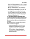
5. Plug Group Access: Determines which Plug Group(s) will be switched when
the Load Shedding feature is triggered. For example, if you have defined
a Plug Group named "test", which includes Plugs B3, B4 and B5, and then
selected the "test" Plug Group via the Plug Group Access parameter, then all
of the plugs in the "test" Plug Group will be switched On or Off whenever the
current load exceeds the Alarm Set Threshold. (Default = undefined.)
Notes:
• In the Text Interface, Plug Group Access is configured by typing 5, pressing
[Enter] and then selecting the desired Plug Group(s) from the resulting
submenu.
• Plug Groups must first be defined (as described in Section 5.6) before they
will be displayed in the Load Shedding menu's Plug Group Access submenu.