


5-2
Basic Configuration
To access command mode via the Text Interface, proceed as follows:
Note: When communicating with the unit for the first time, you will not be
able to contact the unit via Telnet, until you have accessed command mode,
via Local PC or SSH Client, and used the Network Parameters Menu to enable
Telnet as described in Section 5.9.
1. Contact the MPC Unit:
a) Via Local PC: Start your communications program and press [Enter]. Wait
for the connect message, then proceed to Step 2.
b) Via Network: The MPC includes a default IP address (192.168.168.168) and a
default subnet mask (255.255.255.0.) This allows you to contact the unit from
any network node on the same subnet, without first assigning an IP Address to
the unit. For more information, please refer to Section 5.9.
i. Via SSH Client: Start your SSH client, and enter the MPC’s IP Address.
Invoke the connect command, wait for the connect message, then
proceed to Step 2.
ii. Via Telnet: Start your Telnet Client, and then Telnet to the MPC’s IP
Address. Wait for the connect message, then proceed to Step 2.
c) Via Modem: Use your communications program to dial the number for the
external modem which you have connected to the MPC’s Console Port.
2. Login / Password Prompt: A message will be displayed, which prompts you to
enter a username (login name) and password. The default username is "super" (all
lower case, no quotes), and the default password is also "super".
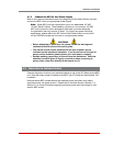
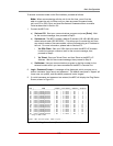
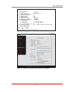
3. If a valid username and password are entered, the MPC will display the Plug Status
Screen, shown in Figure 5.1.
LOCAL - Managed Power Controller Site ID: (undefined)
PLUG | NAME | STATUS | BOOT DELAY | DEFAULT | PRIORITY
-----+--------------------------+--------+------------+---------+----------
A1 | Local_InfeedA_Outlet1 | ON | 0.5 Secs | ON | 1 |
A2 | Local_InfeedA_Outlet2 | ON | 0.5 Secs | ON | 2 |
A3 | Local_InfeedA_Outlet3 | ON | 0.5 Secs | ON | 3 |
A4 | Local_InfeedA_Outlet4 | ON | 0.5 Secs | ON | 4 |
A5 | Local_InfeedA_Outlet5 | ON | 0.5 Secs | ON | 5 |
A6 | Local_InfeedA_Outlet6 | ON | 0.5 Secs | ON | 6 |
A7 | Local_InfeedA_Outlet7 | ON | 0.5 Secs | ON | 7 |
A8 | Local_InfeedA_Outlet8 | ON | 0.5 Secs | ON | 8 |
A9 | Local_InfeedA_Outlet9 | ON | 0.5 Secs | ON | 9 |
A10 | Local_InfeedA_Outlet10 | ON | 0.5 Secs | ON | 10 |
B1 | Local_InfeedB_Outlet1 | ON | 0.5 Secs | ON | 11 |
B2 | Local_InfeedB_Outlet2 | ON | 0.5 Secs | ON | 12 |
B3 | Local_InfeedB_Outlet3 | ON | 0.5 Secs | ON | 13 |
B4 | Local_InfeedB_Outlet4 | ON | 0.5 Secs | ON | 14 |
B5 | Local_InfeedB_Outlet5 | ON | 0.5 Secs | ON | 15 |
B6 | Local_InfeedB_Outlet6 | ON | 0.5 Secs | ON | 16 |
* = Plug in BUSY state
Enter: <CR> for more plugs, <ESC> to quit ...
Figure 5.1: The Plug Status Screen (Text Interface; MPC-20V Shown)