


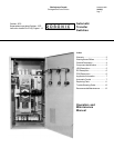
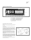

Instruction Leaflet
30-470 (E)
Page 12
Trouble Shooting Guide
Symptoms
refusal to re-transfer to normal
source upon restoration
will not transfer to emergency
source upon failure of normal
source
transfer without a power
failure in the normal source
no time delay when there
should be
engine-generator starts when
the normal source has not
failed
normal source has failed and
the transfer switch cycles
without stopping in emergency
if the power is not available on
the load terminals with either
the normal or emergency
sources available and the
transfer switch will not operate
Possible Causes
a voltage sensing relay did not
energize
emergency to normal time delay
relay has failed
a loose control connection
engine-generator did not start
generator not producing
enough voltage at a high
enough frequency (device CR
is voltage and frequency
sensitive)
a loose control connection
CR device has failed
normal to emergency time delay
relay, if supplied, has failed
if voltage sensing relays
supplied in emergency, there
may be a failure of one
a voltage sensing relay has
failed
emergency to normal time delay
relay has failed
that particular time delay relay
has failed
the engine start time delay relay
has failed
a plant exerciser has been built
into the system
a voltage sensing relay has
failed
the operating cam in the
mechanism has either broken
or come out of the breaker
handle
ELS has failed to operate
the breaker may be complete
with trip units and if there has
been a fault on the system, the
motor circuit has been opened
by either EAS and NAS.
Correct and manually reset the
breakers in the transfer switch
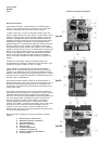
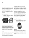
Recommended Maintenance
1. DO NOT perform dielectric tests on the equipment with the control
components in the circuit.
2. DO NOT use loctite.
3. Check lubricant in high speed bearings of the motor and the low
speed bearings of the gear box. For lubrication use Dow Corning
Silicon DC44 or equivalent on the high speed bearings and Aero
Shell No. 6 grease or equivalent in gear box after 5000 operations.
4. Check if control components are tight in sockets.
5. Periodically inspect all terminals (load, line and control) for tightness.
Retighten all bolts, nuts and accessible hardware. Clean or replace
any contact surfaces which are dirty, corroded or pitted.
6. Robonics should be in clean, dry and moderately warm locations. If
signs of moisture are present, dry and clean transfer switch. If
there is corrosion try to clean off, if cleaning is unsuitable replace
the corroded parts. Should dust and/or debris gather on the
transfer switch, brush, vacuum or wipe clean. DO NOT blow dirt
into breaker or terminals.
7. Test the transfer switch operation. While the Robonic is exercising,
check for freedom of movement, hidden dirt or corrosion and any
excessive wear on the mechanical operating parts. Clean, lubricate
or replace parts where necessary.
8. Check all adjustable control components (time delay and voltage
sensing relays) for correct settings.
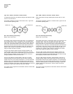
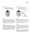
9. If the type RO mechanism is removed be sure that the scribe lines
on the gears are in line. When reassembling the drive mechanisms
be sure that they are fastened to the correct holes in the frame and
that the breaker handles are between the cam fingers (one breaker
has to be on and the other off).
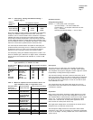
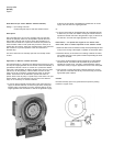
Type LRO Robonics
CAUTION
DO NOT overtighten the pivot screw inside the operating arm. This
screw was correctly adjusted at the factory to provide low friction
movement of the operating arm without excessive play.
DO NOT overtighten the set screw holding the operating cam on the
motor shaft.