


4
2
1
3 4 5 6 7
8
11 1416 12
15
11
10
13 13
9
9
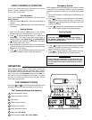
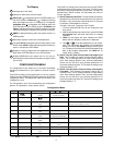
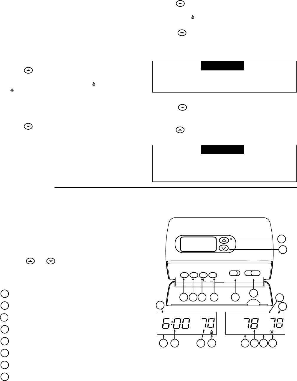
Figure 5. Thermostat display, buttons, and switches
SU
EMERHOLD
PM
SA MALF
FLTR
AM
MO TU WE TH FR
TIME PRGM RUN HOLD
Fltr
FAN
EMER
ON AUTO COOL
OFF HEAT
OPERATION
Do not allow the compressor to run unless the com-
pressor oil heaters have been operational for 6 hours
and the system has not been operational for at least 5
minutes.
Before you begin programming your thermostat, you should be
familiar with its features and with the display and the location
and operation of the thermostat buttons. Your thermostat con-
sists of two parts: the thermostat cover and the base. To
remove the cover, pull it straight out from the base. To replace
the cover, line up the cover with the base and press until the
cover snaps onto the base.
THE THERMOSTAT BASE
Other than and , the following buttons and switches are
located on the bottom of the thermostat cover (see fig. 5).
The Thermostat Buttons and Switches
1
Raises temperature setting.
2
Lowers temperature setting.
3
TIME button.
4
PRGM (program) button.
5
RUN (program) button.
6
HOLD temperature button.
7
FAN switch (ON, AUTO).
8
SYSTEM switch (COOL, OFF, HEAT, EMER).
CHECK THERMOSTAT OPERATION
If at any time during testing your system does not operate
properly, contact a qualified service person.
Turn on power to the system.
Fan Operation
If your system does not have a G terminal connection, skip to
Heating System.
1. Move fan switch to ON position. The blower should begin to
operate.
2. Move fan switch to AUTO position. The blower should stop
immediately.
Heating System
1. Move SYSTEM switch to HEAT position. If the auxiliary
heating system has a standing pilot, be sure to light it.
2. Press
to adjust thermostat setting to 1° above room
teemperature. The Heat Pump system should begin to
operate. However, if the Flame icon (
) and Snowflake icon
(
) are flashing, the compressor lockout feature is operating
(see Configuration menu, item 7).
3. Adjust temperature setting to 4° above room temperature.
The auxiliary heat system should begin to operate and the
Flame icon will be flashing.
4. Press
to adjust temperature setting below room tem-
perature. The heating system should stop operating.
Emergency System
EMER bypasses the Heat Pump to use the heat source wired
to terminal E on the thermostat. EMER is typically used when
compressor operation is not desired, or you prefer back-up heat
only.
1. Move SYSTEM switch to EMER position, EMER will flash on
the display.
2. Press
to adjust the thermostat above room tempera-
ture. The Aux heating system will begin to operate. The
Flame icon (
)will display flashing to indicate that the Aux
system is operating.
3. Press to adjust the thermostat below room tempera-
ture. The Aux heating system should stop operating.
Cooling System
To prevent compressor and/or property damage, if
the outdoor temperature is below 50°F, DO NOT
operate the cooling system.
1. Move SYSTEM switch to COOL position.
2. Press
to adjust thermostat setting below room tem-
perature. The blower should come on immediately on high
speed, followed by cold air circulation
3. Press to adjust temperature setting above room tem-
perature. The cooling system should stop operating.
▲
! CAUTION
▲
! CAUTION