2
INSTALLATION
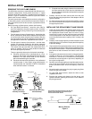
REMOVING THE OLD FLAME SENSOR
The 3049 flame sensors are manufactured with different termi-
nal/panel configurations. Some models have three
1
⁄4” spade
terminals, while others have two
1
⁄4” spade terminals and one pin
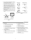
terminal. Figure 5 illustrates the terminal layout and internal
switch action for each variation.
The service technician must identify the terminal configuration
on the existing sensor, and confirm that it matches the replace-
ment. If the sensor terminals do not match, replacement cannot
be made.
Before removing old flame sensor, perform the following:
1. On Type 3049 Flame Sensor - record the color code for
each wire attached to the three quick-connect terminals
and disconnect the wiring. Refer to Fig. 5 for terminal/panel
configurations.
2. For both types of mercury flame sensors - inspect the pilot
burner, flame sensor bulb, and the adaptors and clips used
to hold the bulb within the pilot burner bracket. Note the
exact arrangement of clips and adapters so that the same
arrangement is used for the replacement flame sensor.
3. For both types of mercury flame sensors - note the exact
location and mounting method for the ignition electrode
attached to the pilot burner bracket or flame sensor bulb.
This location must be used when the replacement flame
sensor is installed. Failure to exactly locate the electrode
will cause pilot ignition problems.
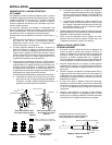
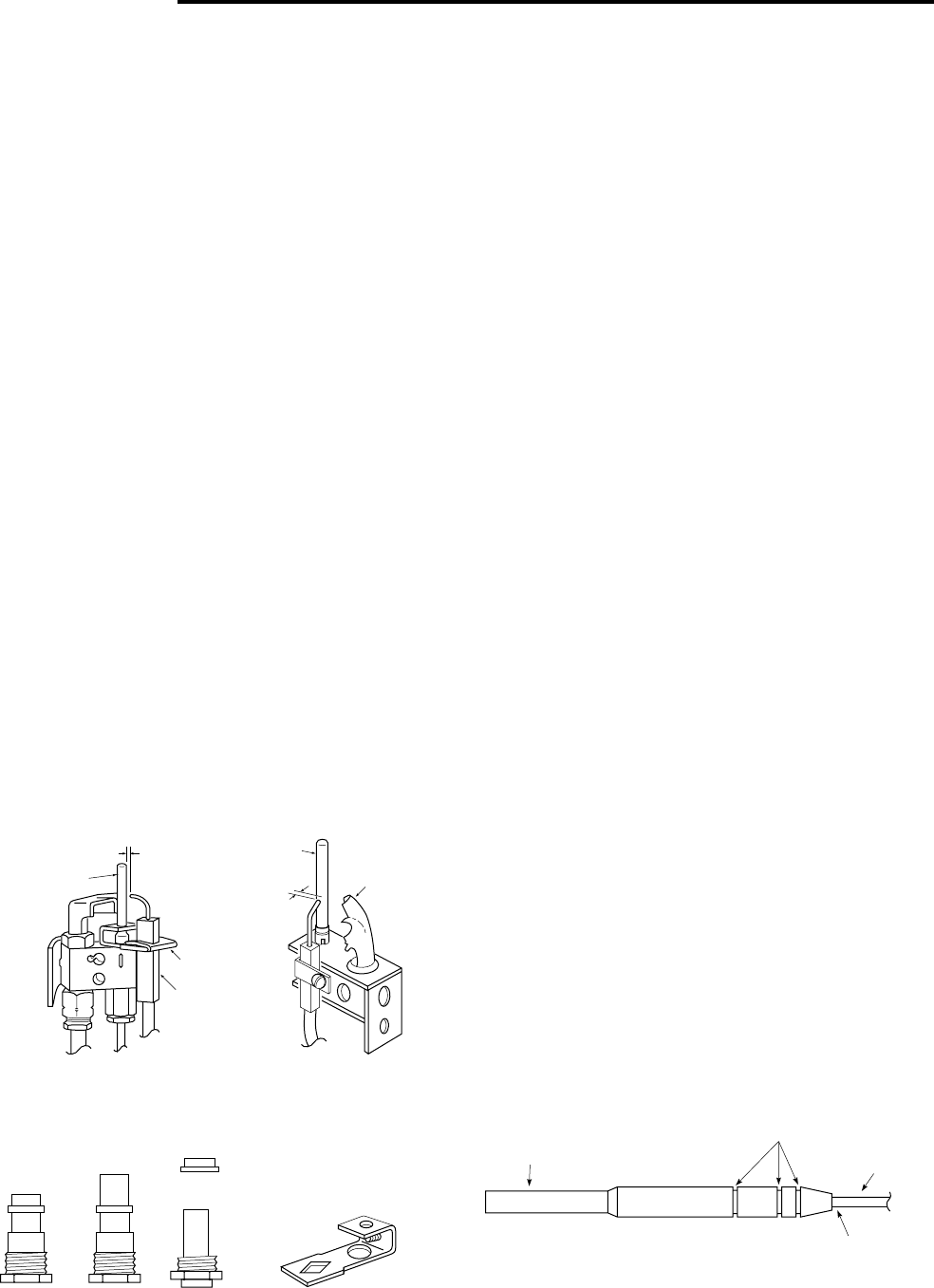
There are generally three styles of electrode mountings:
A. Electrode and pilot burner manufactured as a one-
piece unit. In this case, electrode position should not be
disturbed. The flame sensor bulb can be removed
without disassembling the electrode.
B. Electrode mounted to the pilot burner via a perforated
mounting strap. In most cases using the perforated
mounting strap, the electrode will NOT be disturbed
when the flame sensor is removed.
C. Electrode mounted using the bracket that attaches to
the flame sensor bulb. In this case, the electrode must
be removed before the bulb can be pulled from the pilot
burner bracket.
4. Carefully remove the flame sensor bulb from the pilot
burner bracket noting the positions of the adaptors and the
ignition electrode.
5. For flame sensors with stud-mount sensing bulbs, remove
the nut from the bulb stud and pull the sensing bulb down
through the pilot burner.
INSTALLING THE REPLACEMENT FLAME SENSOR
1. Check the sensing bulb of the defective flame sensor and
note the positions of any C-ring(s) installed on the bulb. If
the replacement flame sensor does not have C-rings,
remove the C-ring(s) from the old flame sensor and install
in the same position on the new flame sensor bulb. Do not
uncoil the new flame sensor capillary until it is ready to be
installed.
2. Carefully uncoil enough capillary to allow installation of the
new flame sensor. Do not kink or sharply bend the capillary
to prevent damage.
3. Slip the bulb of the replacement flame sensor into the pilot
burner bracket and secure it with the same method used for
the defective flame sensor. The bulb should be held by the
pilot burner so that movement from side to side is mini-
mized.
4. If the ignition electrode was removed or changed position,
reinstall it so that it is in its original position. The spark gap
should be
3
⁄32” minimum to
5
⁄32” maximum from the tip of the
electrode to the sensing bulb or pilot hood, depending on
the original configuration.
5. Carefully uncoil enough capillary to install the switch mecha-
nism on the same position as the original unit. Be sure to
prevent excessive strain where the capillary enters the
bulb.
6. Mount the switch mechanism (for plug-in types) plug flame
sensor into gas valve socket.
7. For type 3049 flame sensors, attach the wires to their
respective terminals.
8. Energize the system and observe the pilot burner and
ignition electrode. Sparking should occur in the middle of
the pilot gas stream.
3
⁄
32
" to
5
⁄
32
"
Element (push-in
type only)
Clamp
Electrode
Sensing Bulb
Hood
Electrode Mounted
With Slip-on Bracket
Electrode Mounted Using
Perforated Strap
Figure 1
3
⁄
32
" to
5
⁄
32
"
Pilot Burner Adaptors
Electrode
Mounting Bracket
Fi
g
ure 2
26-0079 26-0080
69-1913
71-1139
NOTE: Part no. 71-1139 is
for use with stud bulb
type pilots
6-1662
Figure 3
Grooves for C-Ring(s)
Mercury Element
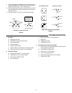
The maximum operating temperature as taken by
thermocouples attached to the automatic pilot
must not be more than shown.
1450°F
500°F
Avoid Bends at This Point


