3
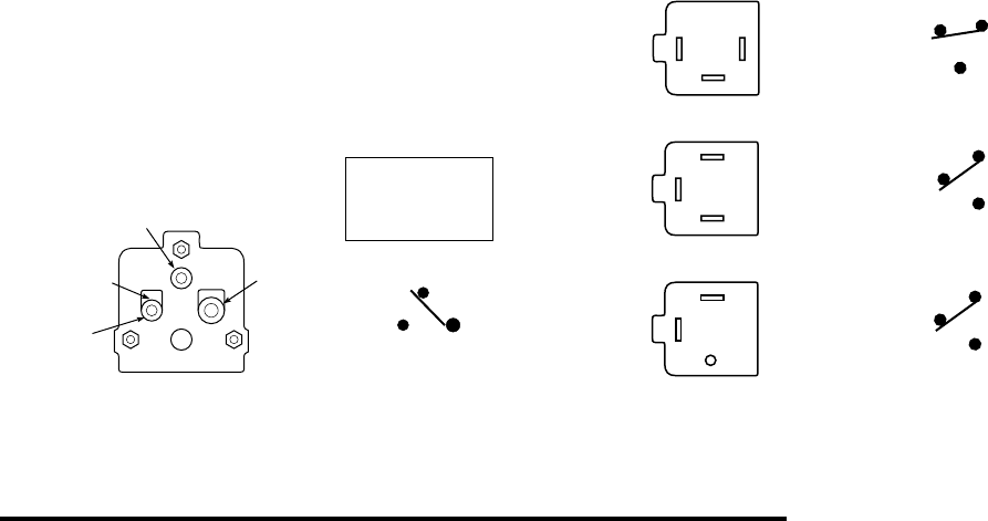
Pin 2
(small)
Pin 3
(small)
Pin 4
(large)
24
3
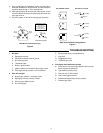
Internal Schematic
4
(COM)
3
(COLD)
2
(HOT)
N.C.
N.O.
175°F
Figure 4
3098 Mercury Flame Sensor Plug
Flame Sensor Action
Pins 4 and 3:
Continuity when Cold
Pins 4 and 2:
Continuity when Hot
9. Once a pilot flame is established, make sure the ignition
electrode REMAINS in the pilot flame, and that the flame
engulfs at least the top
3
⁄4” of the sensing bulb.
10. After approximately 45 seconds, the flame sensor should
receive sufficient heat from the pilot flame and switch the
main gas valve on.
11. Cycle the system on and off to insure proper operation.
TROUBLESHOOTING
1. No Spark
A. Spark gap incorrect
B. Electrode shorted to chassis ground
C. No incoming power
D. Thermostat open
E. Break in ignition cable
F. Ignition cable not connected to pilot relight control
G. Pilot relight wiring incorrect or unit is defective.
2. Pilot will not light
A. No pilot gas at burner - check gas cocks
B. Spark gap incorrect or poorly located
C. Wiring to type 3049 incorrect.
D. No incoming gas
E. Wiring to gas valve incorrect/defective
F. High draft
G. Plugged pilot orifice
H. Defective gas valve.
3. Pilot lights, No main burner ignition
A. Flame sensor not receiving sufficient heat from pilot
flame, Improperly positioned.
B. Type 3049 incorrectly wired
C. Gas cock not in “ON” position
D. Low incoming gas pressure
E. Defective/damaged flame sensor capillary
F. Defective gas valve.
2
3
1
1 (COM)
3 (COLD)
2 (HOT)
N.C.
N.O.
24
3
4 (COM)
3 (COLD)
2 (HOT)
N.C.
3 (COLD)
N.C.
N.O.
24
3
4 (COM)
2 (HOT)
N.O.
3049 TERMINAL PANEL
3049 SWITCH ACTIONS
Figure 5
3049 Terminal/Panel Configurations


