


128
590-00
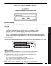
SCREW TERMINALS
Opto-Isolator Inputs - 16 pairs of positive and negative terminals, isolated from ground.
O - Infrared Output - Positive terminal for the IR output signal.
G - Ground - Negative terminal for the IR output signal.
The "O" and "G" terminals drive IR emitters directly or the IR input of Xantech connecting blocks,
IR routers, interface modules, etc.
12VDC - 12 volts output, positive & negative terminals.
INPUTS
A decision as to the type of external input(s) must be
made. Figs. 1 & 2 show some examples. The LED
inside each opto-isolator within the 590 must pass
current in order for the unit to recognize an input. This
is accomplished by applying a momentary 5 to 30
volts DC input to these 16 circuits. While many types
of switch closures to do this are possible, we will
discuss only one for simplicity, the Model 598 key
pad. Fig. 1 shows the 598 providing contact closures
to activate 8 of the 16 opto-isolator inputs.
OUTPUT
The "O" and "G" terminals on the rear panel will drive
IR emitters direct or the SIGNAL IN of Xantech
connecting blocks, controllers, etc. If a single model
282, 283, 284 or 286 Mini-Emitter(s) is to be used, cut
off the plug, strip the leads, and connect the wire with the white stripe to "O" and the black wire to "G". For
the connection of more emitters, use Xantech Connecting Blocks model 789-44 or 791-44. In this case,
connect the "O" and "G" terminals to the "INPUT" and "GROUND", respectively, on the Connecting Blocks.
The 590 output circuit has the same electrical characteristics as the infrared receivers and key pads in
Xantech’s broad line of remote control extension systems and therefore can be wired as part of a larger
system.
TURN IT ON
Plug the power supply into the 12VDC jack on the 590 then plug it into a wall outlet. The five red LEDs
(ERROR, PROGRAM, CONFIRM, DELETE and OUTPUT) on the front of the 590 should be off. If any of
them are on, unplug the power supply from the wall, wait 10 to 15 seconds and plug it in again. Repeat this
process until all of the lamps are off.
PROGRAMMING
Before programming the 590, press the RES (reset) button on the rear panel. This will clear any data stored
during factory testing. Do not push this button again unless you wish to erase ALL of the programming
information which you have entered. There is no way to restore this information except by reprogramming.
NOTE: FOR THE SAKE OF CLARITY, EXTERNAL CONTACT CLOSURES WILL BE REFERRED TO AS
"KEYS" THROUGHOUT THIS MANUAL (whether made with a push-button
or a wire connected to the
+12V DC terminal and held to the + terminal of the desired input. Refer to step 3 following).
Programming Procedure:
1. Press the PGM (program) button on the rear panel. The PROGRAM lamp on the front panel will light.
2. Place the "teaching" hand-held remote control two to four inches in front of the 590. Point it directly
at the internal Infrared Sensor (located just above the OUTPUT LED on the 590's front panel).
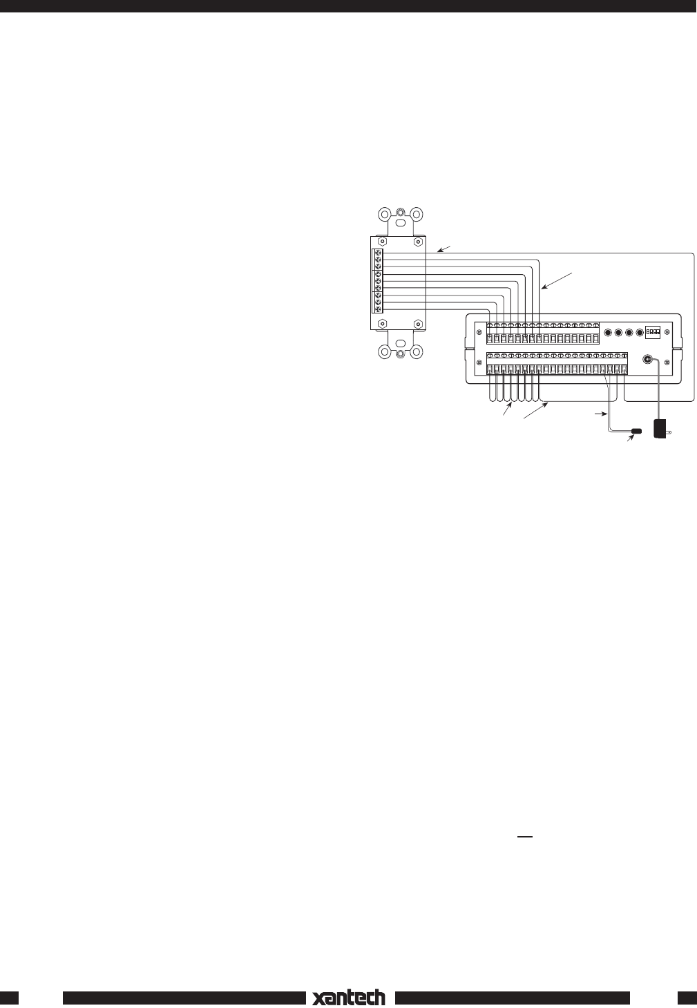
1
12VDC
12VDC
1234
BANK
RES DEL SEQ PGM
+
–
234567891011 141516OG
–+
12 13
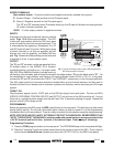
Emitter, Connecting Block, etc.
120 V AC
Unswitched
786-00
Power
Supply
White Striped
Side (output)
C
1
2
3
4
5
6
7
8
C
1
2
3
4
5
6
7
8
Wire size typically AWG 20-24
Model 590
(rear panel)
Model 598
Key Pad
(rear view)
ON
Ground or "–"
return wires. See
Step 3 under
"PROGRAMMING"
+12V DC
Fig. 1 Typical connections when using a 598 Keypad with a
590 Programmable Controller.