


- 14 -
291D SERIES
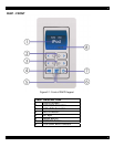
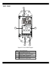
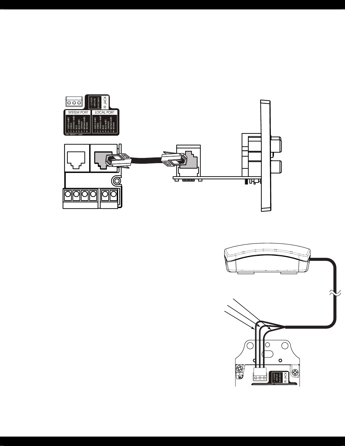
D5KP
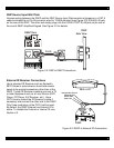
Internal Wire Colors
White IR OUT
Black GND
Red +12V
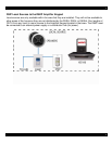
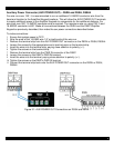
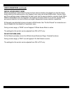
D5IP Source Input Wall Plate
Interconnecting between the D5KP and the D5IP Source Input Plate consists of plugging in a CAT-5
cable terminated to an RJ-45 connector wired to T-568A standard (see Figure 2.0) to the RJ-45 jack
on the rear of the D5IP. The other end simply plugs into the LOCAL PORT RJ-45 jack on the rear of
the zone’s D5KP Amplified Keypad. See Figure 3.2 for details.
D5KP Rear
D5IP
Side View
Cat-5
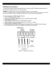
L+
L-
R+
R-
SPEAKERS
PWR IN
+
-
Figure 3.2: D5IP to D5KP Connections
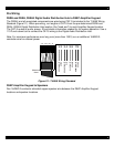
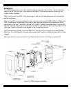
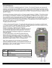
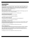
External IR Receiver Connections
Use a standard IR Receiver such as Xantech’s
291D Series in areas where a hand-held remote
needs to be pointed somewhere other than at the
D5KP. Typical IR Receiver locations are near a TV
or other equipment such as a Local Source (DVD
Player, CD Player, A/V Receiver, etc.). Use a
CAT-5 wire to extend the IR Receiver’s cable if
necessary and connect the other end to the D5KP.
Only three conductors of the CAT-5 will be used.
By default, the D5KP External and Internal IR is
active. To disable the External or Internal IR, see
Section 4.0.
Figure 3.3: D5KP to External IR Connections